Moving Load Optimization
Moving load optimization allows you to find the number of loaded lanes and the exact position of vehicles in the transverse direction as well as longitudinal direction, which will give the most critical responses.
Applicable code in Civil 2019 (v1.1): AASHTO Standard, AASHTO LRFD, PENNDOT, Canada, BS, Eurocode, Russia, Australia
Steps to follow for Moving Load Optimization:
1. Define required data here.
2. Define vehicles.
3. Go to the ‘Moving Load Case’ function and select the ‘Moving Load Optimization’ option.
From the Main Menu select Load > Moving Load > Traffic Line Lanes > Moving Load Optimization.
![]() To enter new or additional traffic
line lanes for moving load optimization
To enter new or additional traffic
line lanes for moving load optimization
Click ![]() .
.
![]() To modify previously entered traffic
line lanes
To modify previously entered traffic
line lanes
Select the traffic line lane to be
modified in the dialog box and click ![]() .
.
When ![]() is
clicked, the selected lane elements will be displayed on the screen.
is
clicked, the selected lane elements will be displayed on the screen.
![]() To delete previously entered traffic
line lanes
To delete previously entered traffic
line lanes
Select the traffic line lanes to
be deleted in the dialog box and click ![]() .
.
Data entry method when ![]() is
clicked
is
clicked
![]() Lane Name
Lane Name
Enter
the name of a carriageway to be optimized.
![]() Traffic
Lane Optimization
Properties
Traffic
Lane Optimization
Properties
Optimization Lane
Enter the carriageway width.
Lane Width
Enter the width of single design lane.
Generate Analysis Lanes
Number of Lanes (2^N+1)
N: A whole number to determine the number of lanes in the optimization lane.
Offset from Centerline
Transverse increment of the location of the vehicle centerline. To find the critical position of vehicles, the program will generate the centerlines of vehicles in the transverse direction within the carriageway width. The ‘Anal. Lane Offset’ parameter defines the spacing of the centerlines. The first centerline is generated at the centerline of carriageway width. The second centerline is generated away from the first centerline by the value of "Anal. Lane Offset" to the both left and right side. More centerlines will be generated for the whole carriageway width.
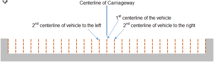
Vehicle centerlines which do not satisfy the requirements of margin and minimum spacing between vehicles will be removed from the vehicle application.
Wheel Spacing
Enter the transverse spacing between the wheels in an axle. For influence line analysis, the program automatically applies a load equal to "Load ÷ no. of wheels" to each wheel.
Margin
Minimum distance between a wheel load and boundary of a single lane. Margin should be so chosen that the sum of vehicle width and 2 times margin does not exceed the single lane width.
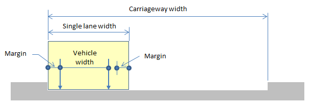
The minimum distance between vehicles is determined as the larger between ‘2 times margin’ and ‘Min. Vehicle Distance’ entered from the ‘Moving Load Case’ dialog.

![]() Eccentricity
Eccentricity
Enter the eccentricity of a traffic line lane relative to a traffic
line lane element.
(-) Negative represents the left side of the traffic line element
and vice versa.
Note
Traffic line lane element is defined as the reference frame element from which the eccentricity is measured.
Straddling Lane Type (BS and Eurocode only)
Check on this option to consider straddling of HB load, special vehicles and Load Model 3.
Impact Factor (AASHTO Standard only)
Enter the impact factors for the entered traffic line lane elements.
![]() Vehicular
Load Distribution
Vehicular
Load Distribution
Assign the means of distributing the vehicular load.
Lane Element: Apply loads to the traffic line lane elements reflecting the eccentricity.
When defining the lanes with lane element type, the vertical load components (vehicle loads) and the moment due to eccentricity is assigned only on the line lane element. Even though the lanes can be located on cross beam elements, if the lane element type is selected, then the distribution effect for the cross beam analysis will not be considered.
Cross Beam: Apply the traffic load to the cross beams.
When using Cross Beam type, the eccentricity is used only for locating the lanes from the line lane element. The vehicle loads are distributed to the girders by cross beam elements defined as a Cross Beam Group. If the user is modeling a bridge having multiple girders, the Cross Beam type is recommended for vehicular load distribution.
Cross Beam Group: Specify the name of the Structure Group to which Cross Beams are assigned. A wheel load is distributed to adjacent cross beams as shown below.
Skew: Specify the Skew Angles at the Start and End of the bridge.
 Moving
Direction
Moving
Direction
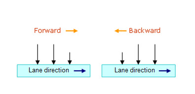
Assign the direction of traffic loads.
Forward: Consider the direction from the Start to End only.
Backward: Consider the direction from the End to Start only.
Both: Consider the both direction.
Selection by
![]() 2
Points: Beam elements
in a line defined by 2 points are assigned as traffic line lane
elements. The first point becomes the Start point.
2
Points: Beam elements
in a line defined by 2 points are assigned as traffic line lane
elements. The first point becomes the Start point.
![]() Picking: Assign the traffic line lane elements
with the mouse. The location of the first-assigned element becomes
the Start point.
Picking: Assign the traffic line lane elements
with the mouse. The location of the first-assigned element becomes
the Start point.
Number: Enter the element numbers pertaining to the traffic line lane elements. The location of the first-assigned elements becomes the start point.
![]() Operations
Operations
The data entry is reflected when Selection by Number is selected.
Add : Add to the selected traffic lane elements with the specified eccentricity and impact factor.
Insert : Insert the selected traffic lane elements in between the previously entered traffic lane elements.
Delete : Select the traffic lane elements at the bottom of the dialog box and delete.
Note
The traffic line lane must be consecutively entered in the direction
of the moving path of the vehicles. When assigning elements with
2 points or Picking [Add] or [Insert] button
need not be clicked.
![]() Span Start
(AASHTO
Standard, AASHTO LRFD, PENNDOT only)
Span Start
(AASHTO
Standard, AASHTO LRFD, PENNDOT only)
For multi-span bridges, select the starting element of each span to distinguish spans. This is used to calculate the maximum negative moment of a continuous bridge due to traffic loads.
Note
The Moving Load Optimization
feature supports following codes:
AASHTO Standard, AASHTO LRFD, Canada, BS, Eurocode and Poland
Standard.
Input Example: