Map Mesh: Face
![]()
Function
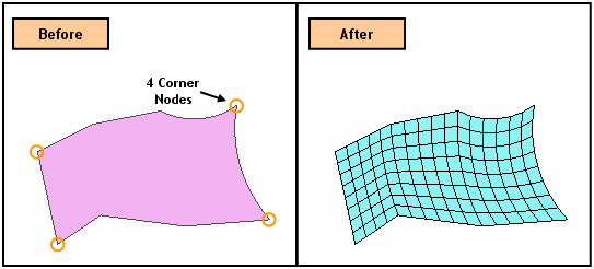
Map-Mesh Face generates mapped meshes on selected faces (Shell, Face).
Call
Main Menu : Mesh > Map Mesh > Face...
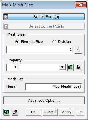
<Map-Mesh Face>
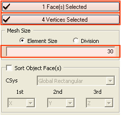
Select Face(s)
Select Faces (Shell, Face), which will be automatically meshed.
Select Corner Points
The Mapped Mesh generating algorithm creates a square mesh by mapping a selected shape into an imaginary square. It then maps the generated mesh back to the original shape. Thus, a group of four edges needs to be defined for mapping each edge of the square. The edges of the face are manually grouped into four edges by selecting four vertices of the edges composing the boundary edges of the face.
Mesh Size
Element Size
Specify the element size.
Division
Specify the number of divisions at the boundary edges of the shape for a meshing operation.
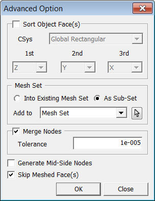
Sort Object Faces
Specify the order of Map Mesh generation. If Map Mesh is generated in multiple Faces in a random order, it often fails due to unmatched number of seeding between Faces. Therefore, defining the order will resolve it is recommended to specify the order.
CSys
Choose the reference coordinate system between the Global Rectangular System and the Global Cylindrical System.
1st
Select the first direction to be considered for sorting.
2nd
Select the second direction to be considered for sorting.
3rd
Select the third direction to be considered for sorting.
Skip Meshed Face(s)
Check this option to avoid generating a Mesh on the face which is assigned a Mesh already.
Notes
Mapped Mesh Algorithm
First, appropriate seeding is assigned to the face for which mapped mesh will be generated, and the corner vertices are assigned. The corner vertices are indicated as A, B, C and D in Fig (i). The seeding between the corners A & B and between the corners A & D are assigned 4 and 12 respectively.
The mapped mesh generating algorithm then maps the selected face into a square and generates a 2-D mesh reflecting the seeding as shown in Fig (ii). The mesh of the square domain is again mapped into the object domain as shown in Fig (iii).
A main reason for failing to generate a mapped mesh is attributed to unmatched division numbers of elements for cross-faced edges. In the above example, the number of divisions for the edge A-B and edge C-D is 4. Similarly, the division number is identical for the edges A-D and B-C. Otherwise, the rectangular meshing is not feasible in the square domain.