Analysis Case: Linear Buckling
![]()
Function
Define an Analysis Case for Linear Buckling Analysis.
Call
Main Menu: Analysis > Analysis Case - Linear Buckling...
Analysis Case for Linear Buckling Analysis will be created. In this command, analysis model data and analysis control will be defined.
<Add/Modify Analysis Case-Linear Buckling>
Specify model data sets for Linear Buckling Analysis. The data can be added/removed per set unit.
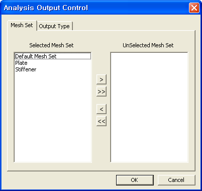
Output Control
Specify Mesh Sets and Output Types which are to be outputted in the result file. By default, all Mesh Sets and all Output Types are selected.
Output Type
Select the output types of Linear Buckling Analysis. midas FEA spends more analysis time and generates larger result files if many output types are selected.
Bucking Modes
Critical Load Factors
Displacement
Reactions
Elemental Forces
Elastic Strains
Stresses
Equivalent Stresses
Von Mises Stress and Maximum Shear Stress ('Maximum principal stress - minimum principal stress' / 2)
Principal Stresses
Equivalent Strains
The sum of principal strains
Principal Strains
Stress / Strain Calculation Locations
Element Center
Nodes
Analysis Control
Click ![]() button to define detail options of Analysis Control.
button to define detail options of Analysis Control.
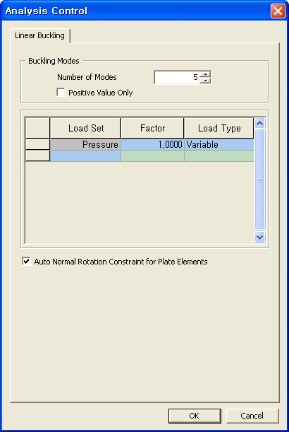
<Linear Buckling Analysis Control>
Buckling Modes
Number of Modes
Enter the number of modes to be calculated.
Positive Value Only
Produce the eigenvalue results only for the loading direction.
<Load Set, Factor, Load Type>
Specify Scale Factors and Load Types for Load Sets used in Buckling Analysis
There are two kinds of Load Type, Variable and Constant. Variable represents loading due to external force or pressure, and Constant accounts for static loading such as Body Force(Selfweight). It is necessary to differentiate a Load Set between Constant and Variable because Constant make influence on Geometric Stiffness, but not related to Critical Buckling Coefficient.
Auto Normal Rotation Constraint for Plate Elements
In order to prevent unnecessary Buckling Modes, this option will restrain rotational degree of freedom on Plate elements. When Plate Element Property has been defined with "Consider Drilling DOF" option (Property > 2D).
Notes
To define detailed setting of the analysis, please click Analysis Control.