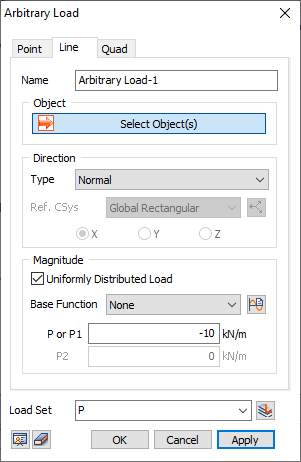
[Object]
Select
objects to assign arbitrary load.
[Direction]
Type
Normal
Ref.
CSys
Select
the coordinate system which becomes the reference of the
load components. Click  button to the
right to prompt the Coordinate
System dialog box to add, modify or delete
the reference coordinate system. button to the
right to prompt the Coordinate
System dialog box to add, modify or delete
the reference coordinate system.
Direction
Edge
Face
[Magnitude]
Uniformly Distributed Load
Check
this option to distribute a uniform load.
Base
Function
If
the load is defined using a function, select the relevant
function. If it is not been created yet, click the  button to invoke the
Create/Modify Function dialog box. button to invoke the
Create/Modify Function dialog box.
P
or P1
Enter
the load value of the starting point or the constant value
for the uniformly distributed load.
P2
Enter
the load value of the ending point.
[Load Set]
Select
a Load Set in which the specified load is included.
|