New for Ver.7.4.1 New for Ver.7.4.1
Function
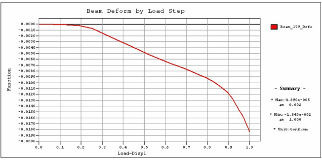
Specify the types of pushover analysis results, and define graphic output functions. Output functions can be also created or changed in Design > Pushover Analysis > Pushover Graph in the post-processing.
Call
Click Define/Modify Function button in the Pushover Graph menu.
Usage
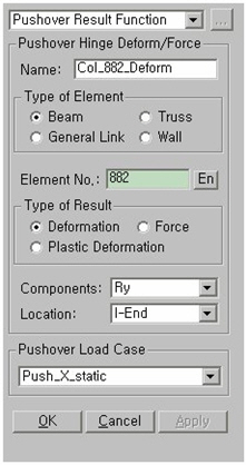
■ When Pushover Hinge Deform/Force is selected [Details…]
|
|
Name : Enter the name of a Graph Function (Pushover Hinge Deform/Force). Type of Element Beam : Select Beam type when pushover hinge type is specified as Beam/Column. Truss : Select Truss type when pushover hinge type is specified as Truss. General Link : Select General Link when pushover hinge type is specified as General Link. Wall : Select Wall when pushover hinge type is specified as Wall element. Element No : Enter the element number, or click in the entry field then select the element from working window. Type of Result Deformation : Total deformation of pushover hinge Force : Member force of an element Plastic Deformation : Plastic deformation of an element (Total deformation of hinge – Yield deformation) Note Plastic deformation is displayed as zero before yielding.
Component
When Deformation is selected The component may be selected from DX, DY, DZ, RX, RY and RZ.
When Force is selected The components may be selected from Axial, Shear-y, Shear-z, Torsion, Moment-y and Moment-z.
Location : Assign a position of the truss element for which analysis results are required. Location is changed according to the specified hinge type.
Select a load case for which pushover graphs will be drawn.
|
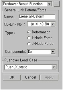
■ When General Link Deform/Force is selected [ Details…]
|
|
Name : Enter the name of a Graph Function (Pushover Hinge Deform/Force). GL-Link No. : Select the General Link element number. Type Deformation : Deformation of General Link I-Node Force : Member force at starting point General Link J-Node Force : Member force at ending point Component : Component may be selected from Axial, Shear-y, Shear-z, Torsion, Moment-y and Moment-z.
Select a load case for which pushover graphs will be drawn.
|
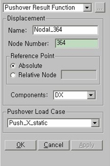
■ When Displacement is selected [Details…]
|
|
Name : Enter the name of a Graph Function. (Nodal displacement) . Node Number : Enter the node number or select the entry field then click the node with the mouse from the working window. Reference Point Absolute : Absolute displacement of the specified node Relative Node : Relative displacement to Relative Node Component : Specify a component direction of displacements. The directions of displacements may be DX, DY, DZ, RX, RY or RZ.
Select a load case for which pushover graphs will be drawn.
|
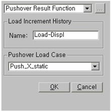
■ When Load Increment History is selected [Details…]
|
|
Name : Enter the name of a Graph Function. (Load Increment History)
Select a load case for which pushover graphs will be drawn.
|
 Pushover Hinge Deform/Force