- When applying Special Provisions for
Seismic Design
2. When Concrete Code Design
or Concrete Code Checking is performed for beam and column
Call
From the Main
Menu select Design
> RC Strong Column-Weak Beam > Ductile Checking.
Usage
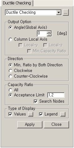
Output Option
Select
a method for generating RC C/B Flexural Capacity Ratio (Refer to Note 1).
Angle(Global
Axis): Display ratios with respect to the global coordinate system.
Column
Local Axis: Display ratios with respect to the element local coordinate
system of the lower column at a beam-column joint.
Local-y:
Display the flexural capacity ratio with respect to the element local
z-axis of the lower column at a joint.
Local-z:
Display the flexural capacity ratio with respect to the element local
y-axis of the lower column at a joint.
Min.
Capacity Ratio: Display the lesser of the flexural capacity ratios
with respect to the element local y- and z-axes of a lower column.
Note
This option becomes activated only when
both Local-y and Local-z are checked on.
Direction
Specify the direction (relative to the joint
node) about which the ratio of flexural capacity of beam is to be calculated.
Min. Ratio
by Both Direction: The lesser of the flexural capacity ratio abut
the clockwise direction and the flexural capacity ratio about the counter-clockwise
direction
Clockwise:
Flexural capacity ratio about the clockwise direction
Counter-Clockwise:
Flexural capacity ratio about the counter-clockwise direction
Capacity Ratio
Select an option for displaying capacity
ratios.
All:
Display flexural capacity ratios for all the nodes of beam-column joints.
Acceptance
Limit: Display flexural capacity ratios that do not exceed the
user-defined flexural capacity ratio (default=1.2).
Search Nodes: Search the nodes whose
flexural capacity ratios are less than the Acceptance Limit (flexural
capacity ratio specified by the user).
Type of Display
Define the type of display as follows:
Values
Display the beam-to-column flexural capacity
ratio in the form of numerical values.
The font and color of the numbers can be controlled
in Display
Option..
Decimal Points:
Assign decimal points for the displayed numbers.
Exp.:
Express as exponentials.
Min &
Max: Display the maximum and minimum values.
Abs Max:
Display the absolute maximum value.
Max:
Display only the maximum value.
Min:
Display only the minimum value.
Limit Scale(%):
Set the screen display limit for flexural capacity ratios relative to
the selected maximum or minimum value
Note
The default Decimal Points can be controlled
in "Preferences".
Legend
Display various references related to analysis
results to the right or left of the working window.
Legend
Position: Position of the legend in the display window
Rank
Value Type: Specify a type of values in the Legend and the number
of decimal points.
Note 1
1. Capacity ratio is not displayed for
the following cases:
When the seismic load case is not included in the
design load combination
When the load case is not
the Strength/Stress Type
When a lower column does
not exist
When a beam member does not
exist
When a wall element is connected
to the beam-column joint
For intermediate nodes of
a member
When a truss element is connected
to the beam-column joint
When material other than
RC is used for member
When a diagonal member (Member
Type=Brace) is used
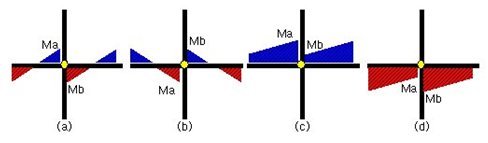
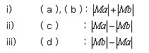
Consider all possible moment
cases for each load combination and calculate as follows
Application of beta angle
i) When
Angle (Global Axis) is selected: Inputted angle becomes the beta angle.
The beta angle (degree) is specified by the user.
ii) When
Column Local Axis is selected: Beta angle is calculated as per the local
axis of the lower column.
For diagonal beam members,
use the values projected to the Global Coordinate System.
[Calculation of column flexural capacity]
Application of beta angle
i) When
Angle (Global Axis) is selected: Inputted angle becomes the beta angle.
The beta angle (degree) is specified by the user.
ii) When
Column Local Axis is selected: When the beta angle of the upper column
is different from that of the lower column, flexural capacity of the upper
column is calculated as per the local axis of the lower column.
 Output Option
.jpg)


 When the load case is not
the Strength/Stress Type
When the load case is not
the Strength/Stress Type  When a lower column does
not exist
When a lower column does
not exist  When a beam member does not
exist
When a beam member does not
exist  When a wall element is connected
to the beam-column joint
When a wall element is connected
to the beam-column joint  For intermediate nodes of
a member
For intermediate nodes of
a member  When a truss element is connected
to the beam-column joint
When a truss element is connected
to the beam-column joint When material other than
RC is used for member
When material other than
RC is used for member  When a diagonal member (Member
Type=Brace) is used
When a diagonal member (Member
Type=Brace) is used