Composite Section for Construction Stage
| ||||
|
| ||||
|
| ||||
|
Define an analytical model for each construction stage by assigning activated or inactivated sections corresponding to each construction stage of a composite bridge.
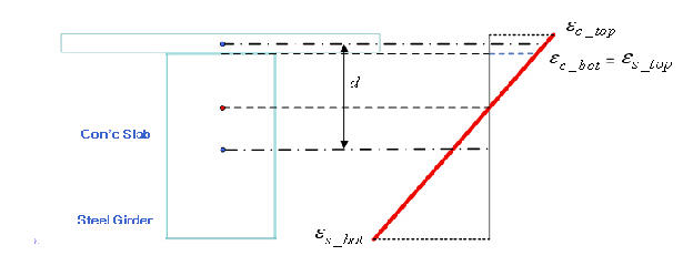
Checking member forces & stresses for each part of a composite section 1. Strain due to a moment applied to a composite section
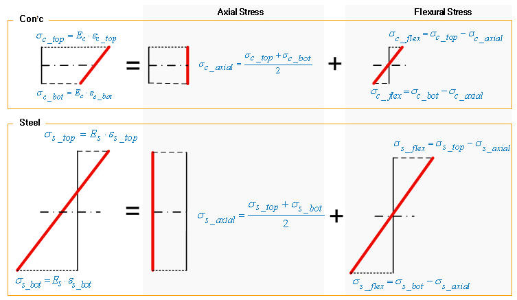
2. Stress calculation for each part
3. Member force calculation for each part The member forces (axial & moment) for each Part are calculated by integrating the stresses shown in the above diagram. Shear forces are not calculated for each part, as the shear flow pattern widely varies depending on the section profile.
The member forces of each Part are calculated on the basis of compatibility of the concrete and steel girder. If the concrete deck and the steel girder are modeled as beam elements, which are rigidly linked, the member forces will not be identical to the above composite concept, unless the spacing of the rigid links approaches 0. | ||||
|
| ||||
|
| ||||
|
| ||||
|
From the Main Menu select Load > Construction Stage Analysis Data > Composite Section for Construction Stage
Select Construction Stage Analysis Data > Composite Section for Construction Stage in the Menu tab of the Tree Menu.
In the Icon Menu select the desired construction stage. | ||||
|
| ||||
|
| ||||
|
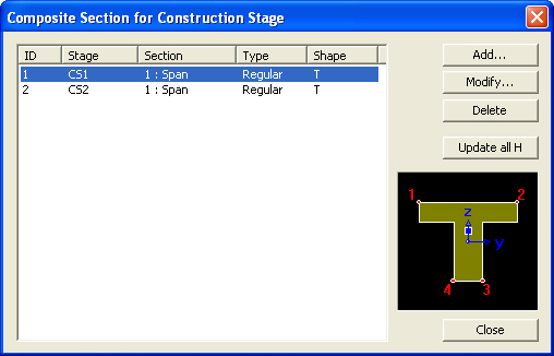
Composite Section for Construction Stage dialog box
Add a new composite section to be used for Construction Stage analysis to the section list.
Modify or check the data for the composite section selected in the list.
Delete the composite section selected in the list.
Recalculate Notational Size of Member, h, using the input section data.
Add/Modify Composite Section for Construction Stage dialog box
Active Stage : Specify the construction stage at which the section becomes activated from the list
Section : Specify the Section from the list.
Composite Type : Specify a Composite Section Type.
Normal : When a Normal Section type is used
User : When the User specifies a section
Section Type : Check the Section Type specified.
Section Shape : Check the Section Shape specified.
Element List : Check the Element Numbers for which the composite section is specified.
|


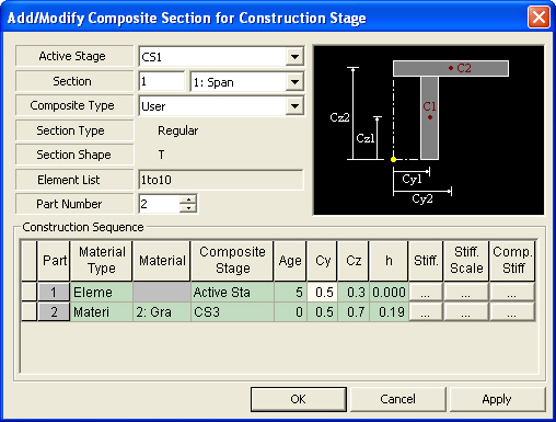
 Construction Sequence
|
|
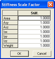
Scale
Area Asy : Effective Shear Area for shear force in the element's local y-direction Asz : Effective Shear Area for shear force in the element's local z-direction Ixx : Torsional Resistance about the element's local x-axis Iyy : Torsional Resistance about the element's local x-axis Izz : Moment of Inertia about the element's local z-direction Weight |
 : Specify
scale factors for the section properties of each Part.
: Specify
scale factors for the section properties of each Part.
|
|
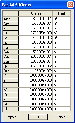
Stiff
Area Asy : Effective Shear Area for shear force in the element's local y-direction Asz : Effective Shear Area for shear force in the element's local z-direction Ixx : Torsional Resistance about the element's local x-axis Iyy : Torsional Resistance about the element's local x-axis Izz : Moment of Inertia about the element's local z-direction Cyp : Distance from the section's neutral axis to the extreme fiber of the element in the local (+)y-direction Cym : Distance from the section's neutral axis to the extreme fiber of the element in the local (-)y-direction Czp : Distance from the section's neutral axis to the extreme fiber of the element in the local (+)z-direction Czm : Distance from the section's neutral axis to the extreme fiber of the element in the local (-)z-direction Qyb : Shear Coefficient for the shear force applied in the element's local z-direction Qzb : Shear Coefficient for the shear force applied in the element's local y-direction |