Setting
Define drawing set which is based on grid function.
▒ Call
|
 After performing analysis,
▒ Detail Description
< Insert DWG Dialog >
|
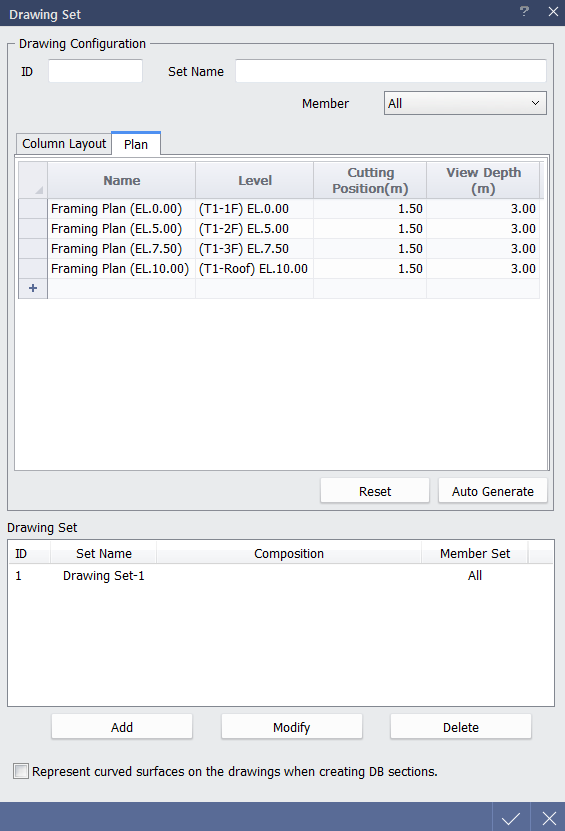
1. Click Auto Generate to list column layout and plan drawing that can be created on the basis of Level Grid information. 2. Create drawing list and click Add to save drawing type which will be outputted from Drawing Set. 3. Click OK to close Drawing Set dialog.
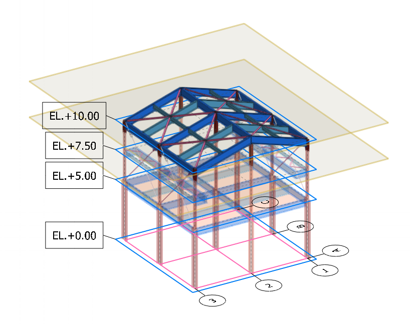
midas nGen drawing output function is based on Grid. If model does not have Grid defined, plan or section drawing cannot be generated correctly. In order to output drawings properly, it is necessary to extract Grid from following path. [Structural] Tab > [Orthogonal Grid] > [Extract Grid]
Elevation or section drawing can be generated on the basis of plan drawing in midas Drawing. |

|
