Point Load 
Apply concentrated loads or moment at each end of line menber(1D).
▒ Call
|
[Load] Tab > [General] > [Point Load] Work Tree [Analysis] Tab > [Static Load] > Right-Click > [Add Point Load]
Work Tree [Analysis] Tab > [Static Load] > [Dead Load] > [Static Load Set] > [Point Load] > [List] > Right-Click > [Modify], [Delete] |

▒ Detail Description
|
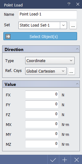
< Point Load Dialog > |
|
|
Direction |
|
|
Select the direction of loads to be applied.
|
|
|
Value |
|
|
Enter the values.
|
 button.

|
|
