Nail (LEM)
Define the Nail (LEM) element for Slope Stability Analysis.
Applicable Modules:
Ground |
Slope |
Soft Ground |
Foundation |
Seepage |
Dynamic |
Stiffness
Reinforcement Spacing
Nail/Pile spacing in the (lateral) direction of the section thickness.
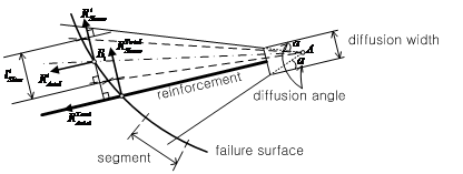
Initial Diffusion Width
Specify the width to account for the diffusion effect of Nail/Pile. Generally the width of bearing plate of Nail/Pile is used. In case of no bearing plate, the diameter of Nail/Pile may be specified.
Initial Diffusion Angle
Angle of stress distribution of Nail/Pile installation which is obtained from tests. Generally, a value in between 10-15 degrees are used.
Adjust Reinf. Effect by F.S.
During iteration to calculate slice forces, reinforcing force can be divided by safety factor resulted from each iteration.
Independent : Input value for
reinforcing force is used in the equilibrium equation. It is suitable
to simulate
reinforcing effect such as reducing
driving force and increasing resisting force right after applying
reinforcements.
Dependent : Reinforcing force
divided by safety factor calculated in the previous iteration
is used in the
equilibrium equation for the next iteration.
It is suitable to simulate reinforcing effect like increasing
resisting
force after deformation occurs rather
than reducing driving force.
Tension Force
Maximum tension strength (material) of Nail/Pile.
Tension/Shear Application Method
Nail
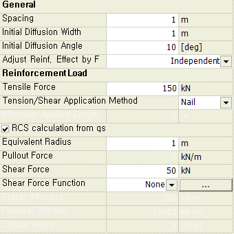
The smaller of the tension force (input) and the pull-out force (calculated from qs or input) is applied as the reinforcing force in the axial direction. Shear force can be applied by specifying a value or defining by a function.
RCS calculation from qs
Equivalent Radius
Converted equivalent radius to calculate the pull-out force resisted by Nail and the surrounding ground
Pull-out Force = qs x π x 2R x Lin , R: Equivalent radius, Lin: Length embedded beyond the failure surface
Shear Force Change
If checked on ![]() , shear distribution changing from
the Nail head can be entered.
, shear distribution changing from
the Nail head can be entered.
Shear Force
Enter a value for shear force based on the length.
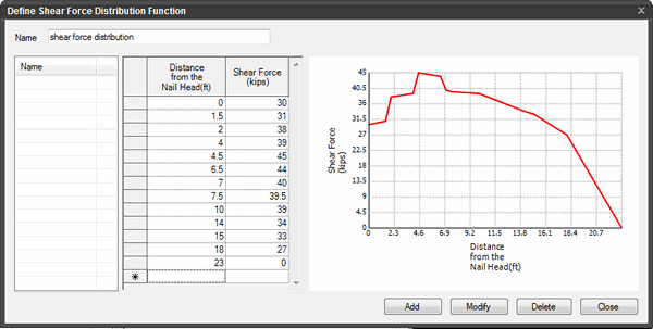
Shear Force Function
Enter a function expressing the change in shear force over the length.
Pile
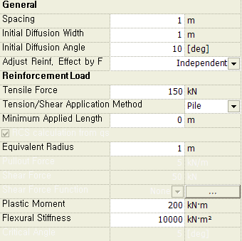
The Shear force is calculated from the plastic moment and the flexural stiffness. Tension force is used only for the upper bound of the shear force (shear force not exceeding 50% of the tension force based on Tresca) and is not used for calculating axial reinforcing force.
Minimum Applied Length
If the embedded length of Pile beyond the failure surface is shorter than the minimum applied length, then the reinforcing force for the corresponding Pile is not considered.
Equivalent Radius
Converted equivalent radius to calculate the pull-out force resisted by Pile and the surrounding ground, which is generally the radius of the bored hole.
Pull-out Force = qs x π x 2R x Lin , R: Equivalent radius, Lin: Length embedded beyond the failure surface
Plastic Moment
Plastic moment (Mp) of Pile.
Flexural Stiffness
Flexural stiffness (EI) of Pile.
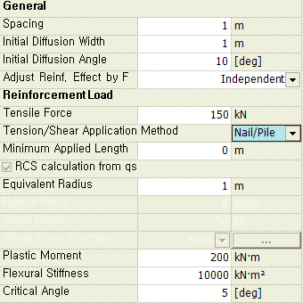
Nail/Pile
Reinforcing force is calculated using the critical angle (θcr) by assessing shear governed (Pile), tension governed (Nail) or tension+shear governed (Nail/Pile).
Minimum Applied Length
If the embedded length of Pile beyond the failure surface is shorter than the minimum applied length, then the reinforcing force for the corresponding Pile is not considered.
Equivalent Radius
Converted equivalent radius to calculate the pull-out force resisted by Pile and the surrounding ground, which is generally the radius of the bored hole.
Pull-out Force = qs x π x 2R x Lin , R: Equivalent radius, Lin: Length embedded beyond the failure surface
Plastic Moment
Plastic moment (Mp) of Nail/Pile.
Flexural Stiffness
Flexural stiffness (EI) of Nail/Pile.
Critical Angle
Enter the critical angle (θcr) to identify shear governed (Pile), tension governed (Nail) and tension+shear governed (Nail/Pile) when calculating the reinforcing force. If the angle (θ) formed by the failure arc tangent and Nail/Pile is greater than π/2-θcr, then it is shear governed. If the angle is smaller than θcr, then it is tension governed. If the angle is greater than θcr and smaller than π/2-θcr, then it is tension+shear governed.
Click for image.
Critical angle is specified to find if Nail/Pile is shear governed, tension governed or governed by both without having to user-define it. The critical angle of 5 degrees or less is generally used.
