Beam Load
Define the Beam Load in an Analysis model.
Beam Load (Force/Moment) may either be a Distributed Load or a Concentrated Load. Select nodes and elements to assign Beam Load. Beam Load cannot be assigned to curves.
Applicable Modules:
Ground |
Slope |
Soft Ground |
Foundation |
Seepage |
Dynamic |
From
the Main
Menu, select Loads
| Boundaries > Loads > Beam Load ![]()
From the Command Line, type 'BeamLoad' or 'BL'
 Load Set
Select the Load
Set under which the Beam Load has to be assigned . Click ![]() to invoke the Define Load Set dialog
to Add, Modify or Delete Load Set(s).
to invoke the Define Load Set dialog
to Add, Modify or Delete Load Set(s).
Select Object
Select the objects to which the beam load will be assigned.
Loading on Curve
Select two nodes to apply a Beam Load.
Loading all the selected Elements
Select two nodes and elements to assign a Beam Load.
Loading by each selected Element
Select elements to assign a Beam Load.
Force/Moment /Distributed Load/Concentrated Load
Select the type of the Beam Load. The diagram and the data entry fields will reflect the selected type of the beam load.
Combination |
x1 |
x2 |
P1 |
P2 |
M1 |
M2 |
Force+Distributed Load |
Y |
Y |
Y |
Y |
-- |
-- |
Force+Concentrated Load |
Y |
-- |
Y |
-- |
-- |
-- |
Moment+Distributed Load |
Y |
Y |
-- |
-- |
Y |
Y |
Moment+Concentrated Load |
Y |
-- |
-- |
-- |
Y |
-- |
Direction
Specify the direction of the Beam Load.
In case of Force
Global X, Global Z, Element Local x or Element Local z can be selected.
In case of Moment
Only about Global Y can be selected.
Projection
This option allows the user whether to apply the Beam Load along the entire beam elements or to apply on the beam elements projected on a line perpendicular to the load direction. This option is available if Select Object is Loading on Curve or Loading by each selected Element.
Yes
To project Beam Load.
No
Not to project Beam Load.
Value
Specify the magnitude of the Beam Load.
Ratio/Length
The loaded location can be entered by relative length ratios or by absolute (real) lengths.
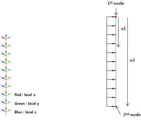
x1
The location at which the Beam Load starts.
x2
The location at which the Beam Load ends.
P1
The magnitude of the Beam Load (Force) at the location x1.
P2
The magnitude of the Beam Load (Force) at the location x2.
M1
The magnitude of the Beam Load (Moment) at the location x1.
M2
The magnitude of the Beam Load (Moment) at the location x2.
![]() Click
Preview to check the created beam load.
Click
Preview to check the created beam load.
![]() The dialog box will be initialized.
The dialog box will be initialized.
![]() After creating the load, the dialog box will close upon clicking.
After creating the load, the dialog box will close upon clicking.
![]() Click the ESC key to close the dialog box.
Click the ESC key to close the dialog box.
![]() After creating the load, the work process will switch to the state
of Select First Node upon clicking.
After creating the load, the work process will switch to the state
of Select First Node upon clicking.
Note: When the Beam Load is of a Distributed type, the Beam Load is consisted of the first location load P1 and the last location load P2. If P1=P2, the Beam Load becomes uniformly distributed but if P1≠P2, the Beam Load becomes linearly distributed. When the Beam Load is of a Concentrated type, then only P1 and M1 are entered.
Beam Load may be assigned in either the Global direction or the Element Local direction. For Global direction, the sign convention is +(→,↑) and -(←,↓), and the + sign applies if the moment is assigned clockwise. If the Beam Load is defined in Element Local axes, the sign convention of the Element Local Coordinate system is applicable.