Steel Flange Reserve Factor (Beam with L. Stiffeners) Table
Generate a table summarizing the structural adequacy for the flanges in beams with longitudinal stiffeners in the cross-section. The table contains two tabs to show the summary for the yielding of the flange plate and the strength of longitudinal flange stiffeners.
From the Main Menu select Rating > Bridge Rating Design > CS454/20 > Steel Bridge > Assessment Result Tables > Steel Flange Reserve Factor (Beam with L. Stiffeners) Table
1. Flange tab
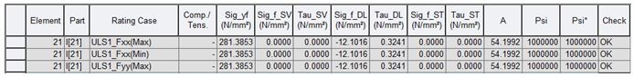
Element: Element ID
Part: The i- or j-end of the element, giving the Node ID at that end in square brackets [Node ID]
Section Type: Compact or noncompact
Rating Case: The relevant Load Combinations for Assessment.
Comp./Tens.: The stress condition in flanges (Compression/Tension).
Sig_yf: The nominal yield stress for the flange material.
Sig_f_SV: The longitudinal stress at the mid-plane of the flange plate due to SV load model.
Tau_SV: The summation of the shear stress (Clause 9.10.2.1, BS5400:3) due to SV load model.
Sig_f_DL: The longitudinal stress at the mid-plane of the flange plate due to combined dead load and superimposed dead load.
Tau_DL: The summation of the shear stress (Clause 9.10.2.1, BS5400:3) due to combined dead load and superimposed dead load.
Sig_f_ST: The longitudinal stress at the mid-plane of the flange plate due to ALL Model 2 loading.
Tau_ST: The summation of the shear stress (Clause 9.10.2.1, BS5400:3) due to ALL Model 2 loading.
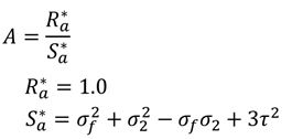
A: Structural Adequacy – calculated as the assessment resistance over the assessment load effects (RA*/SA*).
Psi: Reserve Factor against a special vehicle load model with the associated standard vehicle loading. The symbol hyphen (-) is shown when the shear directions are different between resistance and shear force due to special vehicle.
Psi*: Reserve Factor against a special vehicle load model without the associated standard vehicle loading. The symbol hyphen (-) is shown when the shear directions are different between resistance and shear force due to special vehicle.
Check: An overall indication whether the section passed all checks and is OK or Not Good (NG)
Note
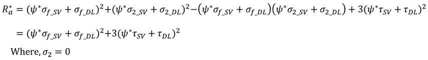
Structural adequacy (A), Psi, and Psi* are calculated as follows. The value of Sig_2 is assumed to be zero.
Psi x S* + SD* + SST* = RA*, Psi is determined with back-calculation from the equation.
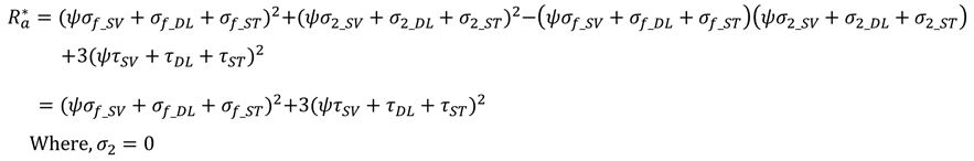
Psi* x S* + SD* = RA*, Psi* is determined with back-calculation from the equation.
2. Stiffener tab
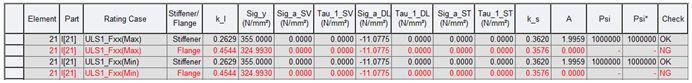
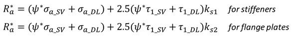
Element: Element ID
Part: The i- or j-end of the element, giving the Node ID at that end in square brackets [Node ID]
Rating Case: The relevant Load Combinations for Assessment.
Stiffener/Flange: Components for the assessment.
k_l: The value of the reduction factor.
Sig_y: The nominal yield stress for the stiffener material or the flange plate material.
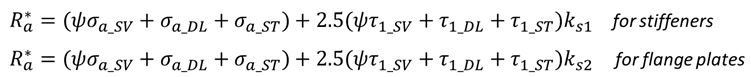
Sig_a_SV: The longitudinal stress at the centroid of the effective section of the stiffener due to SV load model.
Tau_1_SV: The in-plane shear stress in the flange plate due to torsion of SV load model.
Sig_a_DL: The longitudinal stress at the centroid of the effective section of the stiffener due to combined dead load and superimposed dead load.
Tau_1_DL: The in-plane shear stress in the flange plate due to combined dead load and superimposed dead load.
Sig_a_ST: The longitudinal stress at the centroid of the effective section of the stiffener due to ALL Model 2 loading.
Tau_1_ST: The in-plane shear stress in the flange plate due to ALL Model 2 loading.
A: Structural Adequacy – calculated as the assessment resistance over the assessment load effects (RA*/SA*).
Psi: Reserve Factor against a special vehicle load model with the associated standard vehicle loading. The symbol hyphen (-) is shown when the shear directions are different between resistance and shear force due to special vehicle.
Psi*: Reserve Factor against a special vehicle load model without the associated standard vehicle loading. The symbol hyphen (-) is shown when the shear directions are different between resistance and shear force due to special vehicle.
Check: An overall indication whether the section passed all checks and is OK or Not Good (NG).
Note
Structural adequacy (A), Psi, and Psi* are calculated as follows.
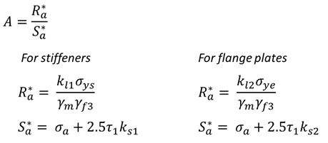
Psi x S* + SD* + SST* = RA*, Psi is determined with back-calculation from the equation.
Psi* x S* + SD* = RA*, Psi* is determined with back-calculation from the equation.