Design Result Tables
Select the elements and assign the residual stress type to determine the plasticity limit and yield limit of the flange plate as per table 5.1.2 of AS 5100.6: 2017.
For Composite Steel Girder Design Check:
Ultimate Limit States:
1. Bending Resistance
2. Resistance to Vertical Shear
3. Resistance to Longitudinal Shear
4. Resistance to Lateral Torsional Buckling
5. Resistance to Transverse Force
6. Resistance to Fatigue
For Composite General Section Design:
Ultimate Limit States:
1. Bending Resistance
2. Resistance to Vertical Shear
3. Resistance to Longitudinal Shear
Serviceability Limit States:
1. Stress Limitation
2. Longitudinal Shear
If AASHTO-LRFD 12 or AASHTO-LRFD 07 is selected
For Composite Steel Girder Design Check:
Span Checking
Total Checking
Strength Limit State:
1. Flexure Resistance
2. Shear Resistance
Serviceability Limit State
Fatigue Limit State
Constructibility
1. Flexure Resistance
2. Shear Resistance
Shear Connector
Longitudinal Stiffener
For I girders and box girders without longitudinal stiffeners:
Moment capacity
Shear capacity
Interaction of shear and bending
Serviceability (Crack Control)
Longitudinal shear (SLS)
Moment capacity (Construction stage)
Shear capacity (Construction stage)
Interaction of shear and bending (Construction stage)
For box girders with longitudinal stiffeners:
Yielding of flange plate
Strength of longitudinal flange stiffeners
Yielding of web panels
Buckling of web panels
Longitudinal web stiffeners
Serviceability (Crack Control)
Longitudinal shear (SLS)
Note
1. The effective width of steel section due to plate buckling is automatically calculated and reflected to calculate bending resistance but not for analysis. Gross section properties for sagging and cracked section properties for hogging are used to calculate stresses to be used for the calculation of effective section properties.
2. The effective widths of both steel section and concrete slab due to shear lag are not automatically considered by the program for both analysis and design.
3. The cracked section properties of concrete slab are considered to calculate hogging bending resistance but not for analysis.
From the Main Menu select Design > Composite Design > Design Result Table
![]() Bending Resistance
Bending Resistance
Bending Resistance tab
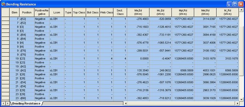
Items produced in the Bending Resistance Table
Elem: Element
Position: I/J-end
Positive/Negative: Positive/Negative moment
Lcom: Load combination
Type: Load combination type (Fxx-max, Fxx-min, ... Mzz-min)
Top Class: Class of top flange
Bot Class: Class of bottom flange
Web Class: Class of web
Sect. Class: Class of cross section
Ma,Ed: The design bending moment applied to structural steel section before composite behavior
Mc,Ed: The part of the design bending moment acting on the composite section
Mpl,Rd: Design value of the plastic resistance moment of the composite section
Mel,Rd: Design value of the elastic resistance moment of the composite section
M_Rd: Design value of the resistance moment of a composite section
Effective Section (Buckling) tab
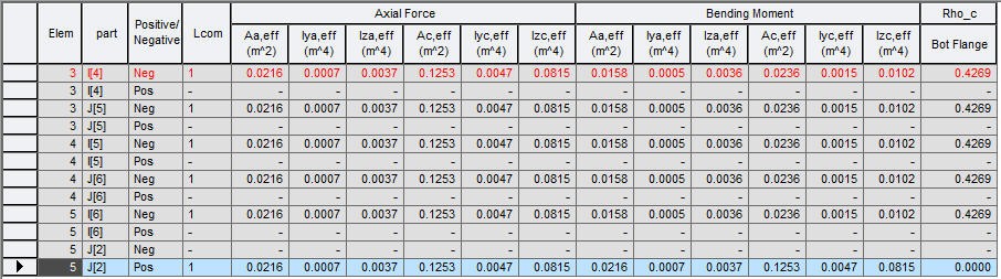
Items produced in the Bending Resistance Table
Elem: Element
Position: I/J-end
Positive/Negative: Positive/Negative moment
Lcom: Load combination
Axial Force: Effective section properties due to buckling when it is subject only to stresses due to uniform axial compression
As,eff: Effective area of steel sections
Iya,eff: Effective moment of inertia of steel sections about the local-y axis
Iza,eff: Effective moment of inertia of steel sections about the local-z axis
Ac,eff: Effective area of composite sections
Iyc,eff: Effective moment of inertia of composite sections about the local-y axis
Izc,eff: Effective moment of inertia of composite sections about the local-z axis
Bending Moment: Effective section properties due to buckling when it is subject only to bending stresses
As,eff: Effective area of steel sections
Iya,eff: Effective moment of inertia of steel sections about the local-y axis
Iza,eff: Effective moment of inertia of steel sections about the local-z axis
Ac,eff: Effective area of composite sections
Iyc,eff: Effective moment of inertia of composite sections about the local-y axis
Izc,eff: Effective moment of inertia of composite sections about the local-z axis
![]() Resistance to Vertical Shear
Resistance to Vertical Shear
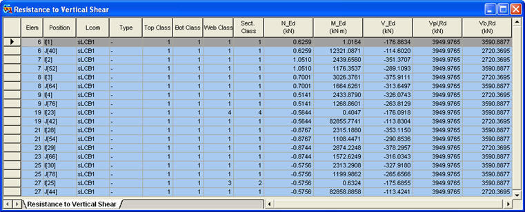
Items produced in the Resistance to Vertical Shear Table
Position: I/J-end
Lcom: Load combination
Type: Load combination type (Fxx-max, Fxx-min, ... Mzz-min)
Top Class: Class of top flange
Bot Class: Class of bottom flange
Web Class: Class of web
Sect. Class: Class of cross section
N_Ed: ![]() , Design value of the compressive normal force
, Design value of the compressive normal force
M_Ed: ![]() , Design bending moment
, Design bending moment
V_Ed: ![]() , Design value of the shear force acting on the composite section
, Design value of the shear force acting on the composite section
Vpl,Rd: Design value of the plastic resistance of the composite section to vertical shear
Vb,Rd: Design value of the shear buckling resistance of a steel web
![]() Resistance to Torsional Buckling
Resistance to Torsional Buckling
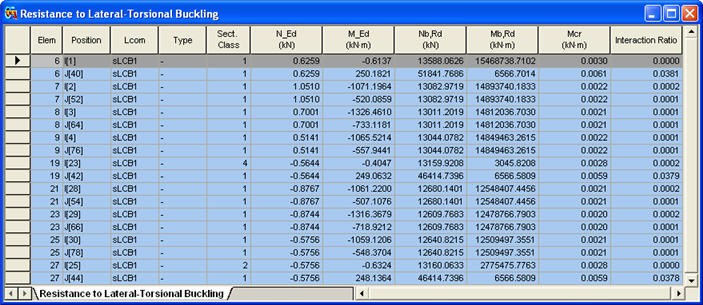
Items produced in the Resistance to Torsional Buckling Table
Elem: Element
Position: I/J-end
Lcom: Load combination
Type: Load combination type (Fxx-max, Fxx-min, ... Mzz-min)
Sect. Class: Class of cross section
N_Ed: ![]() , Design value of the compressive normal force
, Design value of the compressive normal force
M_Ed: ![]() , Design bending moment
, Design bending moment
Nb,Rd: Design buckling resistance of the compression member
Mb,Rd: Design buckling resistance moment
Interaction Ratio: ![]()
![]() Resistance to Transverse Force
Resistance to Transverse Force
![]()
Items produced in the Resistance to Transverse Force Table
Elem: Element
Position: I/J-end
Lcom: Load combination
Type: Load combination type (Fxx-max, Fxx-min, ... Mzz-min)
F_Ed: ![]() , Design transverse force
, Design transverse force
N_Ed: ![]() , Design value of the compressive normal force
, Design value of the compressive normal force
My,Ed: Design bending moment applied to the composite section about the y-y axis
Mz,Ed: Design bending moment applied to the composite section about the z-z axis
F_Rd: Design resistance to local buckling under transverse forces
Eta2: ![]() ,
, ![]()
Eta1: ![]() , Member verification for uniaxial bending (EN 1993-1-5, (4.14))
, Member verification for uniaxial bending (EN 1993-1-5, (4.14))
Interaction Ratio: ![]()
![]() Resistance to Longitudinal Shear
Resistance to Longitudinal Shear
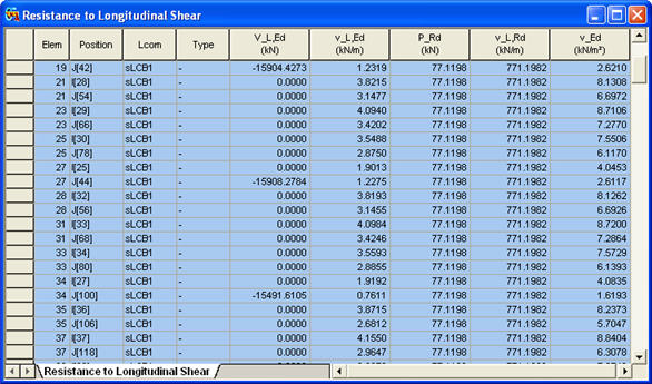
Items produced in the Resistance to Longitudinal Shear Table
Elem: Element
Position: I/J-end
Lcom: Load combination
Type: Load combination type (Fxx-max, Fxx-min, ... Mzz-min)
V_L,Ed: ![]() , Longitudinal shear force acting on length
, Longitudinal shear force acting on length ![]() of the inelastic region
of the inelastic region
v_L,Ed: ![]() , Design longitudinal shear force per unit length at the interface between steel and concrete
, Design longitudinal shear force per unit length at the interface between steel and concrete
P_Rd: ![]() , Design value of the shear resistance of a single connector
, Design value of the shear resistance of a single connector
v_L,Rd: ![]()
v_Ed: ![]() , Design longitudinal shear stress
, Design longitudinal shear stress
![]() Resistance to Fatigue
Resistance to Fatigue
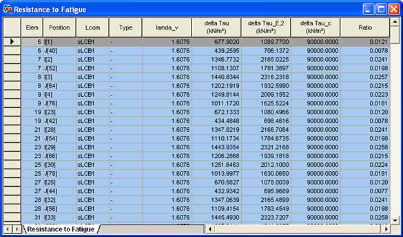
Items produced in the Resistance to Fatigue Table
Elem: Element
Position: I/J-end
Lcom: Load combination
Type: Load combination type (Fxx-max, Fxx-min, ... Mzz-min)
lamda_v: ![]() , Damage equivalent factors
, Damage equivalent factors
delta Tau: ![]() , Range of shear stress for fatigue loading
, Range of shear stress for fatigue loading
delta Tau_E,2: ![]() , Equivalent constant amplitude range of shear stress related to 2 million cycles
, Equivalent constant amplitude range of shear stress related to 2 million cycles
delta Tau_c: Reference value of the fatigue strength at 2 million cycles
Ratio: delta Tau_E,2/ delta Tau_c
![]() Stress Limitation
Stress Limitation
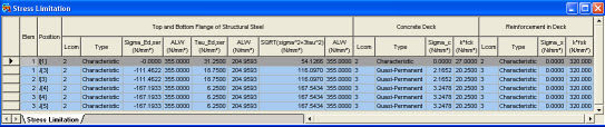
Items produced in the Stress Limitation Table
Sigma_Ed,ser, Tau_Ed,ser: Nominal stresses in the structural steel from the characteristic load combination. Refer to EN 1993-2 7.3.
ALW: Stress limit
Sigma_c: Stress in the concrete deck.
k*fck: Stress limit
Sigma_s: stress in the reinforcement.
k*fsk: stress limit
![]() Longitudinal Shear
Longitudinal Shear
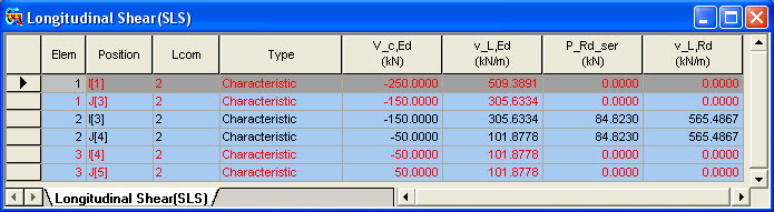
Items produced in the Longitudinal Shear Table
V_c,Ed: Vertical shear force acting on the composite section.
v_L,Ed: Longitudinal shear force per unit length in the shear connector.
P_Rd_ser: Shear resistance of a single shear connector for SLS.
v_L,Rd: Longitudinal shear resistance per unit length for the shear connector.
If AASHTO-LRFD 12 or AASHTO-LRFD 07 is selected
1. Span Checking
(1) by Result Table
▶ Design > Composite Design > Design Result Table...
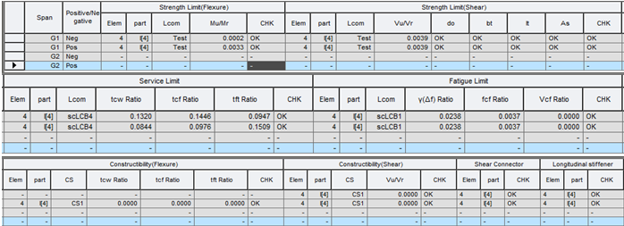
Most critical member results in each span can be viewed in a result table as shown below.
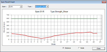
(2) by Span Result Graph
▶ Design > Composite Design > Design Result Diagram...
The results of the span group defined by the span information can be checked here. The flexure and shear results based on distance or node can be checked here. The current applied member force or elasticity is marked in red while the strength or elasticity is marked in green.
2. Total Checking
▶ Design > Composite Design > Design Result Table...
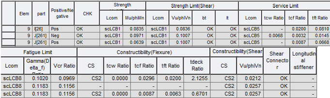
Summary results for each member can be viewed in a result table as shown below.
3. Strength Limit State Result
3.1 Flexure
The results can be viewed in a result table as shown below.
▶ Design > Composite Design > Design Result Tables > Strength Limit State (flexure)…
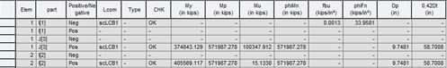
Where,
My : yield moment
Mp : plastic moment
Mu : moment due to the factored loads
phiMn : nominal flexural resistance of a section multiplied by resistance factor, phi, for flexure
fbu : largest value of the compressive stress throughout the unbraced length in the flange under condition, calculated without consideration of flange lateral bending
phiFn : nominal flexure resistance of a flange
Dp :distance from the top of the concrete deck to the neutral axis of the composite section at the plastic moment
Dt : total depth of the composite section
3.2 Shear
The results can be viewed in a result table as shown below.
▶ Design > Composite Design > Design Result Tables > Strength Limit State (shear)…

Where,
Vu : shear due to the factored load
phiVn : nominal shear resistance multiplied by resistance factor, phi, for shear
bt_lim1 : projecting width limit for transverse stiffener, 2.0+(D/30), as per Eq. 6.10.11.1.2-1
bt_lim2 : projecting width limit for transverse stiffener, 16tp, as per Eq. 6.10.11.1.2-2
bt_lim3 : projecting width limit for transverse stiffener, bf/4, as per Eq. 6.10.11.1.2-2
bt : projected width of transverse stiffener as per Article 6.10.11.1.2
lt_lim : limiting moment of inertia of transverse stiffener as per Eq. 6.10.11.1.3-3&4
lt : Moment of Inertia of transverse stiffener as per Article 6.10.11.1.3
4. Service Limit State Result
The results can be viewed in a result table as shown below.
▶ Design > Composite Design > Design Result Tables > Service Limit State…
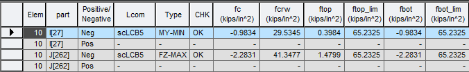
Where,
fc : compression-flange stress
fcrw: nominal bending buckling resistance for webs as per Eq. 6.10.11.9.1-1
fcf : compression-flange stress
fcf_lim : limit of compression-flange stress
ftf : tension-flange stress
ftf_lim : limit of tension-flange stress
5. Fatigue Limit State Result
The results can be viewed in a result table as shown below.
▶ Design > Composite Design > Design Result Tables > Fatigue Limit State...
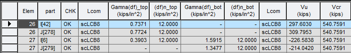
Where,
γ(Δf) : Range of Fatigue Limit State
(ΔF)n : Nominal Fatigue Resistance
Lcom : Load combinations used in the calculation
Vu : shear in the web due to the unfactored permanent load plus the factored fatigue load
Vcr : shear buckling resistance as per Eq. 6.10.9.3.3-1
6. Constructibility Result
6.1 Flexure
The results can be viewed in a result table as shown below.
▶ Design > Composite Design > Design Result Tables > Constructibility (flexure)...
Where,
fbuw : flange stress calculated without consideration of flange lateral bending
phifcrw : nominal bend-buckling resistance for webs
fbuc : compression-flange stress with consideration of flange lateral stress
phifc : limit of compression-flange stress
fbut : tension-flange stress with consideration of flange lateral stress
phift : limit of tension -flange stress
fdeck : longitudinal tensile stress in a composite section deck
phifr : limit of concrete deck tensile stress. fr shall be taken as the modulus of rupture as per the Article 6.10.1.7
6.2 Shear
The results can be viewed in a result table as shown below.
▶ Design > Composite Design > Design Result Tables > Constructibility (shear)...
Where,
Vu : shear in the web due to the factored load
phiVcr : shear-buckling resistance multiplied by resistance factor, phi, for shear
7. Shear Connector Result
The results can be viewed in a result table as shown below.
▶ Design > Composite Design > Design Result Tables > Shear Connector...

Where,
H/D : height to diameter ratio
(H/D)lim : limit value of height to diameter ratio (=4.0)
p : pitch of shear connectors specified by the user
p_lim1: pitch limit value, nZI/(Vsr), as per Eq. 6.10.10.1.2-1
p_lim2: pitch limit value, 6d
s : transverse spacing of shear connectors spacing (Transverse Cross Section)
edge : distance of the top compression flange edge_lim (=1.0 in)
Cover : clear depth of concrete cover over the tops of the shear connectors (> 2.0 in)
Penetration : depth of penetration of the shear connector(>2.0in)
n : number of shear connectors entered in transverse direction
n_Req : required number of shear connectors
8. Longitudinal Stiffener Result
The results can be viewed in a result table as shown below.
▶ Design > Composite Design > Design Result Tables > Longitudinal Stiffener...
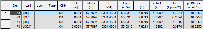
Where,
bl : projecting width
bl_lim : limit of projecting width as per Eq. 6.10.11.3.2-1
I : Moment of inertia of cross-section
I_lim : limit of moment of inertia of cross-section as per Eq. 6.10.11.3.3-1
r : radius of gyration
r_lim : limit of radius of gyration as per Eq. 6.10.11.3.3-2
fs : flexure stress of longitudinal stiffener
phiRhFys : limit of flexure stress as per Eq. 6.10.11.3.1-1
If AS 5100.6: 2017 is selected
1. Ultimate Limit State Results
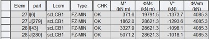
1) Moment Capacity
Where,
M* : design bending moment of a compact section
ϕMb : design member moment capacity of a compact section
fs* : summation of stresses in the critical flange of a not-compact section (fs* is plus when it is compression.)
ϕfy : design yield resistance of the critical flange of a not-compact section
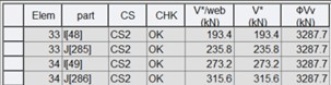
2) Shear Capacity
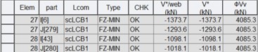
Where,
V*/web : design shear force per web
V* : total design shear force
ϕVv : design shear capacity of a web
3) Interaction of shear and bending
Where,
M* : design bending moment
ϕMs : design section moment capacity
V* : design shear force
ϕVvm : design shear capacity of a web in the presence of bending moment
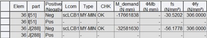
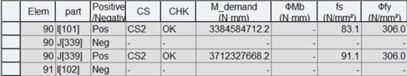
4) Yielding of flange plate
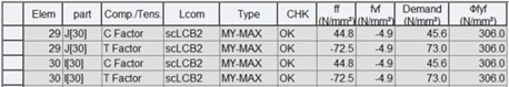
Where,
ff* : longitudinal stress at mid-plane of the flange plate
fvf* : shear stress in the flange due to torsion and shear force on the beam
Demand : demand stress of the flange, ![]() is assumed to be zero.
is assumed to be zero.
ϕfyf : design yield stress of the flange
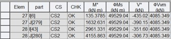
5) Strength of longitudinal flange stiffeners
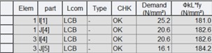
Where,
Demand : demand stress of the stiffener, ![]() whichever is more critical
whichever is more critical
ϕkL*fy : yielding/buckling capacity of the stiffener, ![]() whichever is more critical
whichever is more critical
6) Yielding of web panels
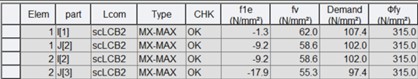
Where,
fle* : effective longitudinal in-plane stress in the plate panel, ![]()
fv* : average design shear stress due to the applied shear force and, in a closed section, due to the applied torsional moment
Demand : demand stress of the panel, ![]() is assumed to be zero.
is assumed to be zero.
ϕfy : design yield stress of the panel
7) Buckling of web panels
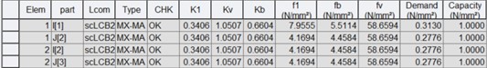
Where,
K1 : axial coefficient
Kv : shear coefficient
Kb : plate buckling coefficient under in-plane bending
fl* : mean longitudinal in-plane stress on a cross section of the panel, but the algebraically higher of the two values on the opposites
fb* : maximum longitudinal stress due to in-plane bending of the panel. The average values over the whole panel is used.
fv* : average design shear stress due to the applied shear force and, in a closed section, due to the applied torsional moment. The average values over the whole panel is used.
Demand : demand value, ![]()
Capacity : capacity value=1.0
8) Longitudinal web stiffeners
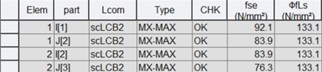
Where,
fse* : equivalent axial stress in the stiffener for buckling as per eq. 7.4.4.2(3)
ϕfLs : design limiting stiffener stress as per figure 7.4.4.2 of AS 5100.6: 2017
2. Service Limit State Results
1) Serviceability (Crack Control)
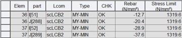
Where,
Rebar : calculated tensile rebar stress at the SLS. Minus value represents tension.
Stress Limit: the larger of the maximum rebar stresses given in Table 9.4.1(A) and Table 9.4.1(B) as per 9.4.1 of AS 5100.5: 2017
2) Longitudinal shear (SLS)
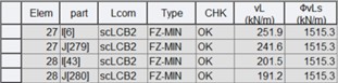
Where,
vL* : design longitudinal shear force per unit length of a composite beam as per eq. 4.8
ϕvLs : permissible longitudinal shear design force per unit length at the serviceability limit state as per eq. 6.8.3.2(2)
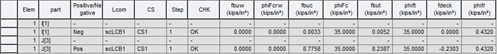
3. Constructibility Results
1) Moment capacity (Construction stage)
Where,
CS : critical construction stage
M* : design bending moment of a compact section at a relevant stage
ϕMb : design member moment capacity of a compact section at a relevant stage
fs* : summation of stresses in the critical flange of a not-compact section at a relevant stage (fs* is plus when it is compression.)
ϕfy : design yield resistance of the critical flange of a not-compact section at a relevant stage
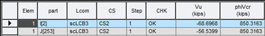
2) Shear capacity (Construction stage)
Where,
CS : critical construction stage
V*/web : design shear force per web at a relevant stage
V* : total design shear force at a relevant stage
ϕVv : design shear capacity of a web at a relevant stage
3) Interaction of shear and bending (Construction stage)
Where,
CS : critical construction stage
M* : design bending moment at a relevant stage
ϕMs : design section moment capacity at a relevant stage
V* : design shear force at a relevant stage
ϕVvm : design shear capacity of a web in the presence of bending moment at a relevant stage