Mesh Generation
![]()
Regardless of dimension and type, the general
process of mesh generation is as shown in the following diagram.

<General Process of Mesh Generation>
The detailed generation process of each 1D, 2D and 3D Mesh is explained below.
1D Mesh
One dimensional elements are generated on the selected edge based on the specified mesh size.
2D Mesh
Before generating 2D mesh, 1D mesh should be created on the boundary edges. The program executes it automatically as a hidden process. Subsequently, 2D mesh fills out the internal area which is bounded by the previously generated 1D mesh. The 2D meshing algorithm can be specified either by the user or automatically by the program.
3D Mesh
After generation of 1D and 2D mesh, the program generates 3D elements in the internal space which is enclosed by the 2D boundary mesh. If necessary, 1D and 2D mesh generations are processed internally by the program.
![]() In simple terms, the generation of 2D and
3D meshes can be viewed as a filling process of internal space of the
lower dimensional boundary elements.
In simple terms, the generation of 2D and
3D meshes can be viewed as a filling process of internal space of the
lower dimensional boundary elements.
![]() In order to generate the proper 2D mesh, 1D
mesh on the boundary edges must be completely closed. Similarly, in order
to generate the proper 3D mesh, the boundary 2D mesh must be completely
closed.
In order to generate the proper 2D mesh, 1D
mesh on the boundary edges must be completely closed. Similarly, in order
to generate the proper 3D mesh, the boundary 2D mesh must be completely
closed.
![]() For convenience, GTS
provides size control for various geometry types, such as Solid, Face
and Edge. However, the predominant factor of determining mesh size is
the size control on the Edges. Therefore, in order to mesh with desired
size properly, it is recommended to specify the mesh size on the critical
edges first.
For convenience, GTS
provides size control for various geometry types, such as Solid, Face
and Edge. However, the predominant factor of determining mesh size is
the size control on the Edges. Therefore, in order to mesh with desired
size properly, it is recommended to specify the mesh size on the critical
edges first.
![]() Once the lower dimensional mesh is created
manually, the higher dimensional mesh can be generated automatically based
on the lower dimensional mesh. If the boundary
2D mesh is created, the 3D mesh can be generated directly with it. Therefore,
theoretically, it is the boundary 2D mesh, and not the Solid (Geometry),
that is required to generate the 3D mesh.
Once the lower dimensional mesh is created
manually, the higher dimensional mesh can be generated automatically based
on the lower dimensional mesh. If the boundary
2D mesh is created, the 3D mesh can be generated directly with it. Therefore,
theoretically, it is the boundary 2D mesh, and not the Solid (Geometry),
that is required to generate the 3D mesh.
Valence indicates the number of elements that are shared by an internal node. Depending on the Valence, the mesh can be divided into two groups, the structured mesh and the unstructured mesh.
Structured Mesh
In a structured mesh, the Valence of internal nodes is constant. The Map Mesh function in GTS generates the Structured Mesh in both 2D and 3D.
Unstructured Mesh
In an unstructured mesh, each internal node
has a different Valence. The Auto Mesh
function in GTS generates the
Unstructured Mesh with various auto-meshing algorithms.
|
|
|
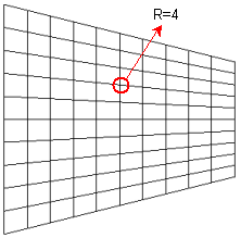
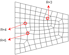
In the structured mesh of the above figure, all internal nodes have a Valence of 4 since they are equally shared by 4 elements. Each element will have a corner angle of about 90 (360 / 4). Such elements with a corner angle of about 90 have an excellent element quality. However, the internal nodes in an Unstructured Mesh may have other Valences (?), such as 3 and 5. Therefore, the engaged elements of each node will have a corner angle of about 120 and 72 (360 /??) accordingly. Thus, as the Valence tends away from 4, the element quality gets worse.
![]() The Valence of 4 appears to be the best in
2D Quadrilateral Mesh (Structured Mesh). If possible, it is recommended
to keep the Valence between 3 and 5.
The Valence of 4 appears to be the best in
2D Quadrilateral Mesh (Structured Mesh). If possible, it is recommended
to keep the Valence between 3 and 5.
The structured mesh has an excellent mesh
quality, but there are a few trade-offs. The following diagram represents
the general process of the structured mesh, and it introduces the required
conditions for the structured mesh.

<General Process of Structured Mesh>
Thus, after transfer the actual 3D geometry to the 2D base geometry, the quadrilateral elements fill up the internal area of the base geometry. Again, the generated quadrilateral mesh will be mapped back to the original geometry. Due to the complicated nature of this method, the original 3D geometry must satisfy the following two conditions.
In order to form the base geometry, 4 corner vertices must be defined.
The number of nodal divisions on an edge or an edge group must be matched with the coupled edge or the coupled edge group (1-3, 2-4).
![]() In case of convex polygons, although GTS automatically detects the 4 corner
vertices, it also provides the user an option to define the 4 vertices
manually.
In case of convex polygons, although GTS automatically detects the 4 corner
vertices, it also provides the user an option to define the 4 vertices
manually.
![]() If the 4 vertices cannot be defined, the geometry
shape must be divided into the applicable shapes, as shown in the following
examples.
If the 4 vertices cannot be defined, the geometry
shape must be divided into the applicable shapes, as shown in the following
examples.
![]() In a 3D structure, 8 corner vertices must
be defined.
In a 3D structure, 8 corner vertices must
be defined.
![]() To construct
a structured mesh, it is recommended to apply the mesh size control using
Number of Divisions rather than the Interval Length, in order to keep
the same number of mesh divisions on each side.
To construct
a structured mesh, it is recommended to apply the mesh size control using
Number of Divisions rather than the Interval Length, in order to keep
the same number of mesh divisions on each side.
Unlike the structured mesh, the unstructured mesh can be applied to any geometrical shape without many regulations, such as the number of divisions and the geometrical structure. Therefore, any complex geometry can be meshed without much effort.