Auto Mesh: Edge
![]()
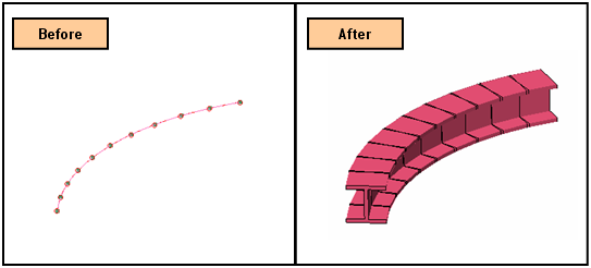
Function
Auto Mesh - Edge automatically generates meshes on selected edges (Wire, Edge).
Call
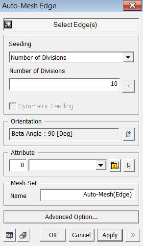
<Auto-Mesh Edge>
Select Edge(s)
Select
Edges (Wire, Edge), which will be
automatically meshed.
Seeding Method
Interval Length
Specify
the element size.
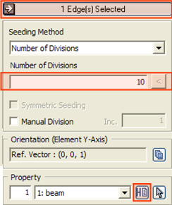
Number of Divisions
Specify
the number of elements to be created along the selected edges.
Linear Grading (Length)
The
spacing of dividing nodes is linearly controlled along the selected edges
by specifying the lengths of the start and end elements.
SLen
SLen
stands for Start Length.
ELen
ELen
stands for End Length.
Div
Div
stands for Division.
CPara
CPara
stands for Concentration Parameter, which defines the range in which Linear
Grading will be applied.
Linear Grading (Ratio)
The
spacing of dividing nodes is linearly controlled along the selected edges
by specifying the length ratio of the start and end elements.
Ratio
Enter the ratio of the element size (length) at the start points of the edges to the size at the end points.
Div
Enter the number of divisions along the selected edges.
CPara
CPara
stands for Concentration Parameter, which defines the range in which Linear
Grading will be applied.
Symmetric Seeding
Symmetric
Seeding is applicable for Linear Grading.
Manual Division
Once
the seeding of edges is displayed, edges can be selected and the mesh
division can be manually changed by the use of the mouse wheel.
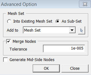
<Advanced Option>