Create Elements
Create elements.
From the Main Menu select Node/Element > Elements > Create Elements.
Shortcut key: [Alt]+1
Click ![]() to the right of Create Elements: Display the Element Table
to the right of Create Elements: Display the Element Table
 Start Node Number
Assign a number to the new starting node created together with new elements in the Model Window. This number is auto-set to the largest node number in use +1. To modify this item, click ![]() and select an option to specify a desired number.
and select an option to specify a desired number.
Start Element Number
Assign a new starting element number. This number is auto-set to the largest element number in use +1. To modify this item, click ![]() and select an option to specify a desired number.
and select an option to specify a desired number.
|
General beam/Tapered Beam: Beam Element/Non-prismatic Beam Element
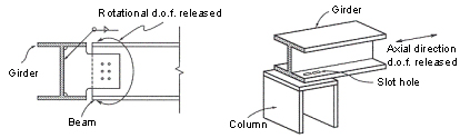
Plate: Plate Element
Thick: Thick plate element
Thin: Thin plate element
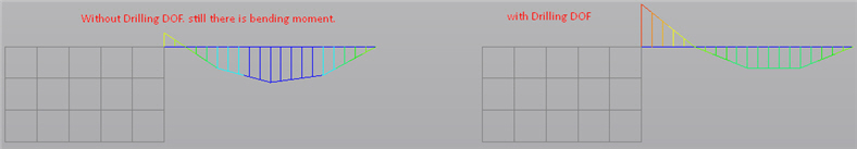
With Drilling DOF: To consider the degree of freedom about the perpendicular direction to the plate
Plane Stress: Plane Stress Element
With Drilling DOF: To consider the degree of freedom about the perpendicular direction to the plate
Plane Strain: 2-D Plane Strain Element
Axisymmetric: 2-D Axisymmetric Element
Solid: 3-D Solid Element
Material
Select a material property number, or select a material property name provided that the material property data have been already defined.
No.: Type in a number on the keyboard or use the mouse to enter the number.
Name: Select a material property name.
Click ![]() to add, inquire, modify or delete material property data. Material properties can be entered either before or after creating elements.
to add, inquire, modify or delete material property data. Material properties can be entered either before or after creating elements.
Section (or Thickness)
Select a section (thickness) number, or select a section (thickness) name provided that the section (thickness) data have been already defined.
No.: Type in a number on the keyboard or use the mouse to enter the number.
Name: Select a section (thickness) name.
Click ![]() to add, inquire, modify or delete section (thickness) data. Section data can be entered either before or after creating elements.
to add, inquire, modify or delete section (thickness) data. Section data can be entered either before or after creating elements.
Orientation
When elements are of a line type (Truss, Beam, etc.), Beta Angle, the coordinates of Reference Point, or Reference Vector are specified to define the orientation of sections.
If the coordinates of the Reference Point are entered, midas Civil internally computes the angle of the point and enters the angle as a Beta Angle automatically.
If the coordinates of the Reference Vector are entered, z-axis of an element is placed on the plane containing the Vector.
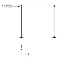
midas Civil uses the Beta Angle (β) conventions to identify the orientation of each cross-section. The Beta Angle relates the ECS to the GCS. The ECS x-axis starts from node N1 and passes through node N2 for all line elements. The ECS z-axis is defined to be parallel with the direction of "I" dimension of cross-sections. That is, the y-axis is in the strong axis direction. The use of the right-hand rule prevails in the process.
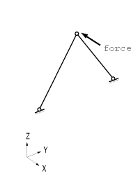
If the ECS x-axis for a line element is parallel with the GCS Z-axis, the Beta angle is defined as the angle formed from the GCS X-axis to the ECS z-axis. The ECS x-axis becomes the axis of rotation for determining the angle using the right-hand rule. If the ECS x-axis is not parallel with the GCS Z-axis, the Beta angle is defined as the right angle to the ECS x-z plane from the GCS Z-axis (See below).
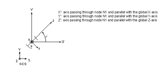
(a) Case of vertical members (ECS x-axis is parallel with the global Z-axis)
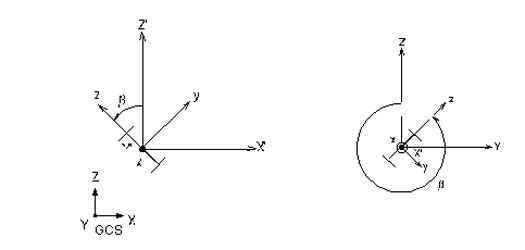
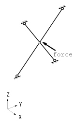
(b) Case of horizontal or diagonal members (ECS x-axis is not parallel with the global Z-axis.)
Beta Angle Conventions
 Nodal Connectivity
Enter the node numbers defining the element in accordance with the (N1, N2,?) sequence shown in the figure that appears upon selecting Element Type.
Use the following two methods to enter the element's nodal connectivity.
-
-
Type in the node numbers in the Nodal Connectivity field.
-
Click the Nodal Connectivity field, which will turn the background color to pale green. Then, assign consecutively the desired node points in the Model Window to enter elements. If there is no node at the assigned point, a new node is created. It is quite convenient to create elements when Point Grid (or Line Grid) , Grid Snap, Node Snap and Elements Snap. are activated.
-
If Ortho option is selected the mouse cursor snaps to the entities oply in the directions parallel to the currently active coordinate axes (UCS or GCS) from the first point selected.
The nodal locations defining the new elements are entered by directional axes, relative distances or element lengths/angles.
x,y,z: The coordinates of the connecting point of an element are entered in the data entry field, then press the enter key on the keyboard or click ![]() .
.
dx, dy, dz: Enter a distance relative to the reference point and press the enter key on the keyboard or click ![]() , If characters are included in the string of numerical values, midas Civil recognizes them as a relative distance, irrespective of which one of the three methods of data entry is selected
, If characters are included in the string of numerical values, midas Civil recognizes them as a relative distance, irrespective of which one of the three methods of data entry is selected
Example: '0,20,10' of ' dx, dy, dz' are expressed as '@10, 20, 10' .
l, theta: l represents the length of an element. Theta represents the angle by which the element direction is rotated with respect to x-axis of the current coordinate system. Once the data are entered, press the enter key on the keyboard or click ![]() .
.
If characters, '@' and/or '<' are included in the string of numerical values, midas Civil recognizes the numbers as l and theta, irrespective of which one of the three methods of data entry is selected.
Example: '10, 15' of 'l, theta' are expressed as '@10<15'
Note
The origin of the current coordinate system is assigned as the reference point initially. Subsequently, the last point used becomes the reference point. To confirm the location of the reference point, enter '@0' in the data field and press the Enter key on the keyboard.
Intersect
If Intersect Node is selected and existing nodes are on the element, the element is divided at the existing nodal positions irrespective of the element type.
If Intersect Element is selected and the line element created intersects with an existing line elements, nodes are automatically created and the line elements are divided at the intersections.
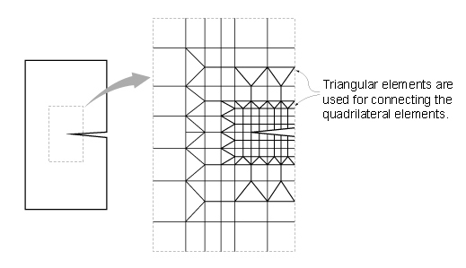
If Create Intersecting Nodes is selected and even if there are no interior nodes in the created plate and solid elements, nodes are created at the intersections of the lines extended by the exterior nodes and plate or solid elements are subsequently created.
.jpg)
Example of Create Intersecting Nodes application
Note 1
Self-weight is applied like uniformly distributed load (external force) using element length, cross section area, and material weight
density.
If we assume that uniformly distributed load is applied to the tens.-only truss element, above the half position will be in tension and the
below the half position will be in compression. Due to the limitation of application in self-weight, tens.-only or comp.-only properties
cannot be considered with self-weight.
As an alternative, we can apply the self-weight using static nodal load with changing weight density of material as zero. If the conversion
of self-weight into nodal load is complex, we can also assign tension-only inelastic hinge (slip bilinear tension) in nonlinear static
time history analysis.
![]() Revision of Civil 2015 (v1.1)
Revision of Civil 2015 (v1.1)
Q1. Can someone explain the idea behind Drilling DOF in detail?