Effective Width
Automatically calculates effective width of Composite section (Steel-Box, Steel-I, Composite-I, Composite-T, Composite-PSC type).
From the section of the girder defined in Span Information, Effective Width automatically calculates the moment of inertia (Iyy) about the y-axis and checks the sectional stresses reflecting the effective width. A scale factor of the new moment of inertia and neutral axis to the original moment of inertia and neutral axis is created. This generates the data for Boundary>Effective Width Scale Factor.
The effective width scale factors calculated here do not support construction stage analysis.
From the Main Menu select Structure > Wizard > Composite Bridge > Effective Width..
Design Code
Following design code can be used:
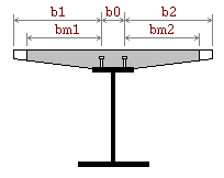
EN 1994-2:2005 (Steel-I Type1, Steel-Box Type 1, Composite-I, Composite-T, Composite-PSC type)
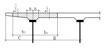
SNiP 2.05.03-84* (Steel-I Type 2 section only)
SP 35.13330.2011 (Steel-I Type 2 section only)
Shear Connector Distance (b0): Required for EN 1994-2:2005
Half Haunch Distance (a): Required for SNiP 2.05.03-84* and SP 35.13330.2011
Scale Factor
Apply the scale factor to the effective width calculated. If the effective width multiplied by the scale factor is larger than the total width, then the total width is used.
Consider the Variation of Centroid
Check on whether to reflect the translation of neutral axis due to considering the effective width. Calculated result is produced as z_top & z_bot Scale Factor in the Effective Width Scale Factor Table.
![]()
Save and display the calculation results of the stiffness considering the effective width.

Stiffness ratio and neutral axis considering the effective width
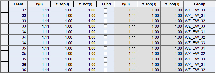
Stiffness ratio considering the effective width