ILM Bridge Model Wizard
ILM Bridge Model Wizard automatically generates the analysis model of a PSC (post-tensioned concrete) bridge by construction stages, constructed by ILM (Incremental Launching Method). The Wizard operates on the basis of entering simple variables. It automatically generates the model data required for a construction stage analysis including the tendon placement and section definition. The construction stages are separately defined by "ILM Bridge Stage Wizard" or "Define Construction Stage".
The Advanced Applications manual illustrates the use of Wizard and the procedure for an ILM bridge analysis.
Note
The input data in ILM Bridge Wizard are saved in the corresponding dialog boxes once the Wizard is executed normally. We can recall the input data after closing the Wizard and subsequently check, modify and re-execute the Wizard. In addition, Wizard data can be saved as a file with .wzd extension, which can be recalled even after closing the program.
From the Main Menu select Structure > Wizard > ILM Bridge > ILM Bridge Model.
![]() Bridge Model Data Type
Bridge Model Data Type
Select a Data Input Type.
When Type 2 is selected, the user can manually define the layout of straight tendon or curved tendons.
![]() ILM Model tab
ILM Model tab
Auto-generate a bridge model by entering the material properties and sections of the main girder and launching nose, launching distances, division of segments, duration of stages, etc.
![]() Bridge Information
Bridge Information
Element Length: length of an element
Note
The lengths of the segments and launching nose are multiple of the one-time launching distance, which is defined in Define Launching Information of ILM Bridge Stage Wizard.
Radius
Check on to specify the radius of a curved bridge with a single curvature, which applies to both main girder and launching nose.
Convex: Convex curvature (center of circle located below)
Concave: Concave curvature (center of circle located above)
Note
The ILM Wizard defines the bridge model as a 3-dimensional curved bridge if the radius is specified. Without the radius, it defines the bridge model as a straight 2-dimensional bridge.
Stage Duration
Specify the number of days it takes to assemble reinforcing steel and formwork, cast and cure concrete, and dismantle the formwork for one segment prior to launching. Note that the time that takes to launch the segment is implicitly included since its duration is minor in nature.
Segment Age
Specify the initial maturity of the segment concrete at the start of each construction stage. It represents the duration for concrete pour to curing prior to launching. The Stage Duration of subsequent stages is used to reflect the passage of time after launching. The Segment Age is used to calculate the time dependent material properties such as creep, shrinkage, modulus of elasticity, tendon stress loss, etc.
![]() Launching Nose
Launching Nose
Material: Specify the Material number for material properties.
Section: Specify the Section number for section properties.
Note
Click the buttons to the right of Material and Section to create new or modify the existing materials and sections.
Length: Specify the length of the launching nose.
Note
Tapered Section Group is automatically assigned to the launching nose during its generation. The Tapered (non-prismatic) section defined in Section is maintained even after the launching nose is divided into a number of elements by the launching distance.
![]() Bridge Model
Bridge Model
Define the material and section of the main girder and the composition of segments.
Material: Material of main girder
Section: Section of main girder
Note
Click the buttons to the right of Material and Section to create new or modify the existing materials and sections.
Segment
Define the units of main girder fabrication corresponding to the individual construction stages.
Note
In an ILM construction, a segment represents the length of girder fabricated in a construction stage at the on-site fabrication plant. One segment corresponds to one construction stage. The Wizard internally creates sub-stages required to launch the full length of each segment reflecting the one-time launching distance. Accordingly, the elements created by dividing the segments must be multiples of the one-time launching distance.
Length: Length of a segment
Repeat: Number of segments to be created repeatedly.
Click ![]() to add the segment input data to the list. The Boundary Condition to the right automatically lists the division points (nodes) of the segments to enable us to input boundary conditions at each launching step. Insert locations may be adjusted by the
to add the segment input data to the list. The Boundary Condition to the right automatically lists the division points (nodes) of the segments to enable us to input boundary conditions at each launching step. Insert locations may be adjusted by the ![]() and
and ![]() buttons. Use Modify and Delete buttons to change or delete segments.
buttons. Use Modify and Delete buttons to change or delete segments.
![]() Boundary Condition
Boundary Condition
Define the boundary conditions to be applied to the construction stage analysis reflecting the on-site fabrication plant, temporary supports, and the piers and abutments of the completed (post-construction stage) structure. The boundary condition for the completed structure can be separately modified in the corresponding construction stage (post-construction stage).
☐ If Final is selected define the boundary condition representing the piers and abutments.
Distance
Referenced to the completed structure, Distance represents the distances from the start (left end - origin) abutment of the bridge to the individual nodes. The distances are automatically calculated and listed by the input data in Segment. Select the locations to which the boundary conditions are assigned (locations of piers and abutments for the completed structure) and click the ![]() after entering the following information:
after entering the following information:
Click the ![]() to delete the boundary condition of the selected location. Multiple selections are possible by the use of the [Ctrl] key.
to delete the boundary condition of the selected location. Multiple selections are possible by the use of the [Ctrl] key.
Temporary Boundary Position
Temporary Boundary Position represents the temporary piers and supports for the launching nose and prefabrication plant. Note that the launching direction is from the right end abutment to the left end abutment (origin of the bridge). The Length for the No.1 position retains the absolute distance from the origin and represents the right end abutment, which is the right end of the completed bridge. The Length for the No.2 and beyond represents the incremental distances from the right end abutment to the temporary piers to the right.
Type
Select the type of boundary condition. The components of the degrees of freedom (dof) are defined in the global coordinate system (Node Local Axes if predefined).
None
No boundary condition applies.
Support
Check in the appropriate boxes to constrain the desired degrees of freedom.
Dx: dof in GCS X-axis (Node Local x-Axis)
Dy: dof in GCS Y-axis (Node Local y-Axis)
Dz: dof in GCS Z-axis (Node Local z-Axis)
Rx: Rotational dof about GCS X-axis (Node Local x-axis)
Ry: Rotational dof about GCS Y-axis (Node Local y-axis)
Rz: Rotational dof about GCS Z-axis (Node Local z-axis)
Point Spring
Define the elastic support stiffness conditions for each dof.
SDx: Elastic support stiffness in GCS X-axis (Node Local x-Axis)
SDy: Elastic support stiffness in GCS Y-axis (Node Local y-Axis)
SDz: Elastic support stiffness in GCS Z-axis (Node Local z-Axis)
SRx: Elastic support rotational stiffness about GCS X-axis (Node Local x-Axis)
SRy: Elastic support rotational stiffness about GCS Y-axis (Node Local y-Axis)
SRz: Elastic support rotational stiffness about GCS Z-axis (Node Local z-Axis)
Elastic Link
Specify Elastic Link elements.
Elastic Link Length
Enter the length of an elastic link element. It is used only to display the element on the screen and does not affect the analysis results.
Link Type
General Type
A general elastic link element is created. Enter the stiffness of the elastic link element in the local element axes (SDx, SDy, SDz, SRx, SRy & SRz).
Rigid Link
Infinitely stiff element condition is assigned. The degrees of freedom are slaved and as such no stiffness needs to be entered.
Tens.-Only
A tension-only elastic link element is created. The axial stiffness (SDx) of the elastic link element is entered. A sufficiently large value (1.0 x 10¹⁰ KN/m) may be entered.
Comp.-Only
A compression-only elastic link element is created. The axial stiffness (SDx) of the elastic link element is entered. A sufficiently large value (1.0 x 10¹⁰ KN/m) may be entered.
Beta Angle: Enter "Beta Angle" to define the local element coordinate system of the elastic link element.
ILM Bridge Model Wizard automatically creates Element Group, Boundary Group and Load group to generate the model data. Refer to Define Structure Group, Define Boundary Group and Define Load Group.
![]() Top & Bottom Tendon tab - Type 1
Top & Bottom Tendon tab - Type 1
Define the type of PSC (prestressed and post-tensioned concrete) box, and define the properties, locations, arrangement type and stressing method of the top and bottom tendons (First phase tendons), which are stressed during the launching stages.
![]() Type
Type
None: No tendons are used.
One Cell: No interior web is present.
Two Cell: A single interior web partitions the PSC box.
![]() Tendon Property
Tendon Property
Select the tendon type
Top
Tendons in top flange
Bottom
Tendons in bottom flange
Note
Click the ![]() button to the right of the selection field to prompt the "Tendon Property" dialog box to add, check or modify the tendon properties.
button to the right of the selection field to prompt the "Tendon Property" dialog box to add, check or modify the tendon properties.
![]() Tendon Arrangement
Tendon Arrangement
Arrangement Type
Define the method of stressing the tendons.
2 Cycle: In the plan view, a group of every second tendons (alternating 50% of the total tendons) is stressed at a stage. The first group of 50% of the total tendons is stressed in the first segment on an alternating basis initially. The second group of the remaining 50% of the total tendons is stressed over the first and second segments. Each group of the tendons is stressed on an alternating basis at each stage over two segments for the subsequent stages except at the last segment. The last stage retains the reverse of the first stage.
3 Cycle: In the plan view, a group of every third tendons (one third of the total tendons) is stressed at a stage. The first group of one third of the total tendons is stressed in the first segment on the every-third-tendon basis initially. The second group of one third of the total tendons is stressed over the first and second segments. The third group of the remaining one third of the total tendons is stressed over the first, second and third segments. Each group of the tendons is stressed on the every-third-tendon basis at each stage over three segments for the subsequent stages except at the two last segments. The last two stages retain the reverse of the first two stages.
Tendon A Jacking Order
From the diagram in the dialog box, select the tensioning order for the tendon group containing the outer-most top tendon (Tendon A) depicted in green. The tensioning order may be first or second for the 2 cycle and first, second or third for the 3 cycle. Tendon B Jacking Order
Tendon B Jacking Order
From the diagram in the dialog box, select the tensioning order for the tendon group containing the outer-most bottom tendon (Tendon B) depicted in green. The tensioning order may be first or second for the 2 cycle and first, second or third for the 3 cycle.
![]() Jacking Stress
Jacking Stress
Specify the tensioning stresses for the top and bottom tendons.
Su: Ultimate tensile strength of tendons
Sy: Yield strength of tendons
![]() Grouting
Grouting
Once the ducts are grouted, the transformed section properties are subsequently considered. The input signifies the timing of incorporating the transformed properties.
Prestressing step
Grouting takes place at the time of tensioning the tendons.
Every n Stage
Grouting takes place at every n stages. If n=1is entered, the grouting is assumed to take place at the next stage after the corresponding tendons are stressed. If n=2 is entered, the grouting is assumed to take place at the third stage after the two corresponding segments have been stressed.
B1, B2, B3, ...
Referring to the guide diagram, input the number of tendons and dimensions to define the tendon placement.
Note 1
Enter '0' for B3 and B5 if an odd number of tendons is placed. In the case of an even number of tendons, enter one half of the tendon spacing.
Note 2
Tendon placement may be defined by the "Tendon Profile" function.
![]() Top & Bottom Tendon tab - Type 2
Top & Bottom Tendon tab - Type 2
Define the type of PSC (prestressed and post-tensioned concrete) box, and define the properties, locations, arrangement type and stressing method of the top and bottom tendons (First phase tendons), which are stressed during the launching stages.
![]() Tendon Arrangement
Tendon Arrangement
Arrangement Type
Define the method of stressing the tendons.
2 Cycle: A group of every second tendons (alternating 50% of the total tendons) is stressed at a stage.
3 Cycle: A group of every third tendons (one third of the total tendons) is stressed at a stage.
Tendon A Jacking Order
From the diagram in the dialog box, select the tensioning order for the tendon group containing the outer-most top tendon (Tendon A) depicted in green. The tensioning order may be first or second for the 2 Cycle and first, second or third for the 3 Cycle.
Tendon B Jacking Order
From the diagram in the dialog box, select the tensioning order for the tendon group containing the outer-most bottom tendon (Tendon B) depicted in green. The tensioning order may be first or second for the 2 Cycle and first, second or third for the 3 Cycle.
![]() Jacking Stress
Jacking Stress
Specify the tensioning stresses for the top and bottom tendons.
Su: Ultimate tensile strength of tendons
Sy: Yield strength of tendons
![]() Grouting
Grouting
Once the ducts are grouted, the transformed section properties of tendon and grout are subsequently considered. The input signifies the timing of incorporating the transformed properties.
Note
From Construction Stage Analysis Control, specify whether to apply gross section or net section/transformed section for calculating section properties.
Prestressing step
Grouting takes place at the time of tensioning the tendons.
Every n Stage
Grouting takes place at every n stages. If n=1is entered, the grouting is assumed to take place at the next stage after the corresponding tendons are stressed. If n=2 is entered, the grouting is assumed to take place at the third stage after the two corresponding segments have been stressed.
Define Tendon Property
If Tendon Property has not been defined, click this button to define the Tendon Property.
Number of Cell
Number of Cells of PSC Box Section defined in Section tab
Symmetric
Select this option when the web tendons at each side are symmetrical.
Ht: Vertical distance from the top edge of the section to the top tendon
Hb: Vertical distance from the top end of the section to the bottom tendon
Position: Select either Top or Bottom.
Baseline(m): Enter the Baseline position, which will become a reference to simplify horizontal tendon placement.
Bli(m): Among the tendons located at the left part of the web, enter the horizontal distance between the Baseline and the tendon, which is closest to the Baseline. Input a positive value regardless of the direction.
Nli: Enter the number of tendons located at the left part of the web.
Bri(m): Among the tendons located at the right part of the web, enter the horizontal distance between the Baseline and the tendon, which is closest to the Baseline. Input a positive value regardless of the direction.
Nri: Enter the number of tendons located at the right part of the web.
ai: Enter the tendon spacing.
Tendon Property: Select the Tendon Property Type.
![]() Web Tendon tab - Type 1
Web Tendon tab - Type 1
Define the second phase tendons placed in the webs of a PSC box section. Tendons are defined for a single web, which are applied symmetrically. If 2 Cell is used, the tendons are placed also in the middle web by horizontal projection.
![]() Type
Type
Select the type of tendon placement in the longitudinal direction.
None: No tendons are placed.
Type1, Type2: Refer to the diagram to the left.
![]() Tendon Property
Tendon Property
Define the tendon type. Click the ![]() .button to the left of the selection field to prompt the "Tendon Property" dialog box to add, check or modify the tendon properties.
.button to the left of the selection field to prompt the "Tendon Property" dialog box to add, check or modify the tendon properties.
1st Tendon
Select the type of web tendon placement. If Type 1 is selected, specify the type of tendon to be placed at the upper most layer. If Type 2 is selected, the 2nd tendon is assumed to be equal to the 1st tendon.
2nd Tendon
Assign the type of tendon to be placed at the mid layer. The entry is valid only if Type 1 is selected.
3rd Tendon
Select the type of web tendon to be placed at the lower most layer. The entry is valid only if Type 1 is selected.
![]() Jacking Stress
Jacking Stress
Specify the tensioning stress for the web tendons.
Su: Ultimate tensile strength of tendons
Sy: Yield strength of tendons
![]() Position
Position
Define the location of tendons to be placed in the web of a PSC box section.
Ey, Theta
Define the plane in which the 2nd phase tendons are placed referring to the guide diagram to the right in the dialog box.
H, G1, G2
Referring to the guide diagram, enter the dimensions required to define the layout of the tendons in the longitudinal direction.
Note 1
The dimensions, a and b, in the input description diagram represent the zones of straight tendon placement at the anchorage and are specified if Type 2 is selected.
Note 2
The tendon placement may also be defined by the "Tendon Profile" function.
![]() Grouting
Grouting
Once the ducts are grouted, the transformed section properties are subsequently considered. The input signifies the timing of incorporating the transformed properties.
Prestressing step
Grouting takes place at the time of tensioning the tendons.
Every n Stage
Grouting takes place at every n stages. If n=1is entered, the grouting is assumed to take place at the next stage after the corresponding tendons are stressed. If n=2 is entered, the grouting is assumed to take place at the third stage after the two corresponding segments have been stressed.
![]() Cell Type
Cell Type
Define the web tendon placing method by specifying the number of cells (webs) of the PSC box section.
1 Cell type or 2 Cell type
![]() Web Tendon tab - Type 2
Web Tendon tab - Type 2
Define the layout of straight or curved tendons by entering the distances from the top and bottom of the girder, the angle of inclination of the tendons and the radii of curvature at inflection points.
![]() Type
Type
Select the type of tendon placement in the longitudinal direction.
None: No tendons are placed.
Type1, Type2: Refer to the diagram to the left.
![]() Tendon Property
Tendon Property
Define the tendon type. Click the ![]() .button to the left of the selection field to prompt the "Tendon Property" dialog box to add, check or modify the tendon properties.
.button to the left of the selection field to prompt the "Tendon Property" dialog box to add, check or modify the tendon properties.
1st Tendon
Select the type of web tendon placement. If Type 1 is selected, specify the type of tendon to be placed at the upper most layer.
2nd Tendon
Assign the type of tendon to be placed at the mid layer. The entry is valid only if Type 1 is selected.
3rd Tendon
Assign the type of tendon to be placed at the mid layer. The entry is valid only if Type 1 is selected.
![]() Grouting
Grouting
Once the ducts are grouted, the transformed section properties of tendon and grouting are subsequently considered. The input signifies the timing of incorporating the transformed properties or the timing of grouting tendons.
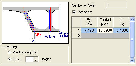
Number of Cell
Number of Cells of PSC Box Section defined in Section tab
Symmetric
Select this option when the web tendons at each side are symmetrical.
Eyi
Enter the horizontal distance from the center of the section to the center of the web. As shown in the guide diagram above, the offset point located to the left is taken as positive and the right is taken as negative. The (-) sign is used only if the section is non-symmetrical.
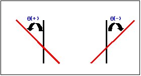
θi
Enter the angle of inclination of the web tendons. The sign convention is illustrated in the figure below.
ai
Enter the horizontal distance from the web center to the tendon. If the tendon is located to the left of the web center, the sign is negative. The right side is given a positive sign.
![]() G1~G4, C1~C3, R1~R3, S1,~S4, Theta1~Theta2
G1~G4, C1~C3, R1~R3, S1,~S4, Theta1~Theta2
Referring to the guide diagram, enter the dimensions required to define the tendon layout.
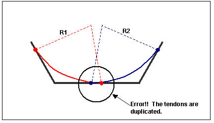
Note
In case where tendon layout cannot be defined:
As shown in the figure below, when the tendons are overlapped because of large curvature radii, the tendon layout cannot be defined.
![]()
![]()
Open the data saved as in the *.wzd file type in the ILM Model Wizard. By using this function, we can re-execute midas Civil and subsequently check and modify the previously entered data within the Wizard.
![]()
![]()
Save the data entered in the ILM Model Wizard as the *.wzd file type.