Response Spectrum Load Cases
Enter the load cases, spectrum functions and loading directions for response spectrum analysis.
The procedure for response spectrum analysis in Civil 2006 is outlined below.
1. Enter mass data using various ways provided in the Main Menu, Model>Masses.
2. Enter the number of modes and necessary data for eigenvalue analysis in Eigenvalue Analysis Control.
3. Define spectrum data to be applied in Response Spectrum Functions.
4. Set options related to response spectrum analysis in Response Spectrum Load Cases.
5. Perform analysis by clicking ![]() Perform Analysis or using the Main Menu, Analysis>Perform Analysis.
Perform Analysis or using the Main Menu, Analysis>Perform Analysis.
6. When an analysis is completed, analyze the results using load cases or load combinations with various post-processing functions from the Results menu.
From the Main Menu select Load > Seismic > Response Spectrum Load Cases.
|
|
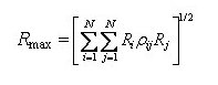
Enter the method of mode combination and specify whether to restore the signs of response spectrum analysis results. Modal Combination Type: Set the method of combining modes in the response spectrum analysis.
SRSS: Square Root of Sum of the Squares
SRSS method, which is most commonly used, renders close approximations of design response for a structure exhibiting well-distributed natural frequencies. However, it tends to overestimate or underestimate the combination for a structural system with close natural frequencies, which can be found in a multi-span bridge with continuous short spans. Another drawback is that it looses signs in the process of combination. CQC: Complete Quadratic Combination
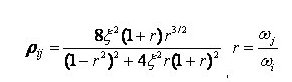
Where
CQC method considers the probabilistic correlation between modes for a structural system with close natural frequencies, which can be found in a multi-span bridge with continuous short spans. By applying the correlation factor in combination using close natural frequency ratios, the overestimating or underestimating problem can be resolved. As shown in the equation above, the correlation factor will become 1 irrespective of the damping ratio when i=j, and it will become identical to SRSS method when the damping ratio is 0. ABS: ABsolute Sum
ABS method renders the largest responses among different combination methods. The signs are neglected by the use of absolute values. It tends to overestimate the response results. When a specific ratio such as the 100:30 rule, etc. is applied after combining the analysis results in each direction considering the directionality of earthquake, the maximum response is obtained by summing the absolute results in three directions. Linear: Linear Sum
In linear method, the user chooses specific modes and enters the Mode Shape Factors directly, which are then linearly combined. The signs are preserved. It is used to check the effects of a specific mode or compare responses by modes. Add signs(+,-) to the Results Specify whether to restore the signs deleted during the mode combination and specify the restoration method Along the Major Mode Direction: Restore the signs according to the signs (+, -) of the principal mode for every loading direction. Along the Absolute Maximum Value: Restore the signs according to the signs of the absolute maximum values among all the modal results. Note In general, structural characteristics can be reflected properly by using the Along the Major Mode Direction option and using the sign of the major mode that greatly contributes to the structural behavior. However, when torsion is considerable due to the structural irregularity, or the modes are closely spaced and the major mode is not very distinctive, the Along the Major Mode Direction option can partially distort the structural behavior. In such a case, it is desirable to opt for Along the Absolute Maximum Value option. Select Mode Shapes Select modes for modal combination. Using the Select Mode Shapes option, linearly combine the modes while entering the Mode Shape Factors directly. |
![]() Spectrum Functions
Spectrum Functions
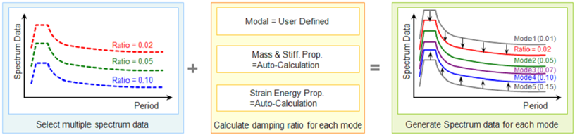
Select pre-defined design spectrum functions, which will be used to define a number of response spectrum load cases. A same spectrum from a code may result in a number of spectrum functions depending on the damping ratio. Therefore, this becomes useful when the user wishes to define a number of spectrum functions based on different damping values in a structure.
 Apply Damping Method
Damping Method : Define the damping property of a structure.
Mass and Stiffness Proportional
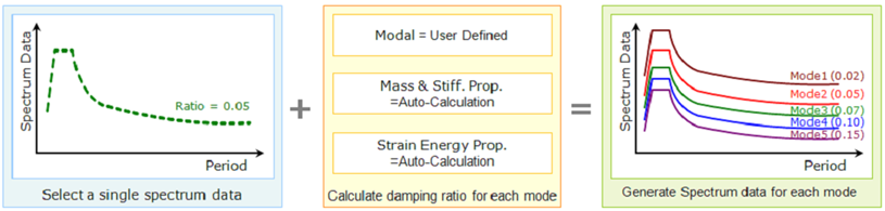
Correction by Damping Ratio : When a single spectrum is selected, a modifying equation is used to adjust the spectrum to apply to each mode having a corresponding damping ratio.
![]()
Note 1
The modifying equation can not be used when multiple spectrums are selected because the spectrums are interpolated based on the damping ratios. A damping ratio can not go beyond the upper and lower bound damping ratios of the spectrum.
Note 2
When combining modal responses, using Complete Quadratic Combination (CQC) will reflect damping for each mode without the use of the modifying equation. The combining method can be specified in Modal Combination Control.
Interpolation of Spectral Data
Select the method of interpolating the response spectrum load data.
Linear : Linear interpolation method
Logarithm : Log-scale interpolation method
![]() Description
Description
Enter a short description
Operation
![]() Enter new or additional response spectrum analysis load cases
Enter new or additional response spectrum analysis load cases
Enter the above entries and click ![]() .
.
![]() Modify previously entered response spectrum analysis load cases
Modify previously entered response spectrum analysis load cases
Select a response spectrum analysis load case from the list in the dialog box and click ![]() .
.
![]() Delete previously entered response spectrum analysis load cases
Delete previously entered response spectrum analysis load cases
Select a response spectrum analysis load case from the list in the dialog box and click ![]() .
.
In addition to the spectrum functions and the loading conditions of the response spectrum, access the following functions to enter additional data required for a response spectrum analysis:
![]() : Eigenvalue Analysis Control... is invoked to check dynamic properties of a structure.
: Eigenvalue Analysis Control... is invoked to check dynamic properties of a structure.
![]() : Response Spectrum Functions... is invoked to define spectrums.
: Response Spectrum Functions... is invoked to define spectrums.