Resultant Force Diagram
Check the resultant forces at several virtual sections defined along the girder using Section for Resultant Forces function. The resultant forces of a section consisting of plate/plane stress elements and beam/truss elements can be checked for Static Load, Settlement Load, Moving Load (AASHTO STANDARD/LRFD, Eurocode, BSCODE 5400 & 3701, CANADA, PENNDOT, AUSTRALIA, and TAIWAN), Response Spectrum Load and Construction Stage Load.
Note
In case of model file consisting of moving load and plate elements, software uses concurrent forces for resultant force calculation.
From the Main Menu select Results > Results > Forces > Resultant Force Diagram
![]() Load Cases/Combinations
Load Cases/Combinations
Select a desired load case, load combination or envelope case.
The Construction Stage applicable for the output of the construction stage analysis is defined in Select Construction Stage for Display or Stage Toolbar. Click  to the right to enter new or modify existing load combinations. (Refer to "Load Cases / Combinations")
Note 1
Resultant Force Diagrams are available for ADD and Envelope type in General, Steel and Concrete load combinations tab. ABS and SRSS load combination types are not applicable for this feature.
Note 2
When results are produced in max, min and all in such cases as moving loads, support settlements and Envelope load combinations, selecting "all" produces resultant force diagrams displayed in absolute values of member forces irrespective of the signs of member forces. In order to produce beam diagrams reflecting the signs, check on "Consider Signs in Load Combination Type of Envelop "all" of Tools>Preference>Environment>Results.
Step
Specify the step for which the resultant force diagrams are to be produced. The Step is defined in geometric nonlinear analysis as Load Step, and additional steps are defined in the construction stages of bridges or heat of hydration analyses.
Note
The Construction Stage applicable for the output of the construction stage analysis is defined in Select Construction Stage for Display or Stage Toolbar.
![]() Components
Components
Select the desired member force component among the following:
Fx: Axial force in the virtual beam’s local x-direction
Fy: Shear force in the virtual beam’s local y-direction
Fz: Shear force in the virtual beam’s local z-direction
Mx: Torsional moment about the virtual beam’s local x-axis
My: Bending moment about the virtual beam’s local y-axis
Mz: Bending moment about the virtual beam’s local z-axis
Note
The local axis of virtual beam is always oriented along ‘I’ end to ‘J’ end of the virtual sections enclosing the virtual beam. The orientation of local axis of virtual beam can be reversed by switching Direction Vector of virtual sections at the two ends of that beam defined in Section for Resultant Forces function.
![]() Options
Options
Scale Factor: Magnify or reduce the size of the diagram graphically displayed in the model window.
Values: Display the member forces of virtual beams in numerical values.
Reverse: Reverse the resultant force diagram display direction.
Top Alignment: Check this option to align the resultant force diagram along the topmost nodes of the virtual sections. If this option is checked off, the resultant force diagram will be aligned on the centroid f the virtual sections.
![]() Output Section Location
Output Section Location
Display the resultant force values at i-end, j-end or both ends.
Note
If the virtual section does not lie on the nodal position, Resultant Force Diagram can be displayed in uneven shape as shown below. It is because the program calculates resultant force using the nodal forces. In order to prevent the uneven diagram, it is recommended to generate virtual section lie on the nodal position.
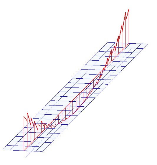
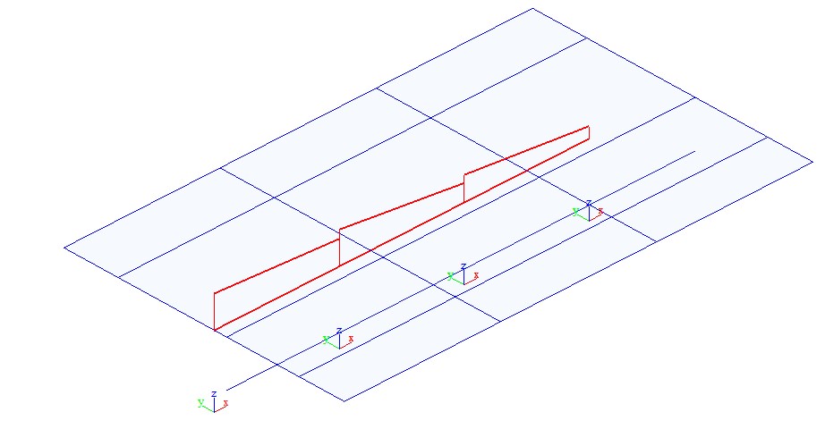
Uneven resultant force diagram when virtual section lie in the middle of elements
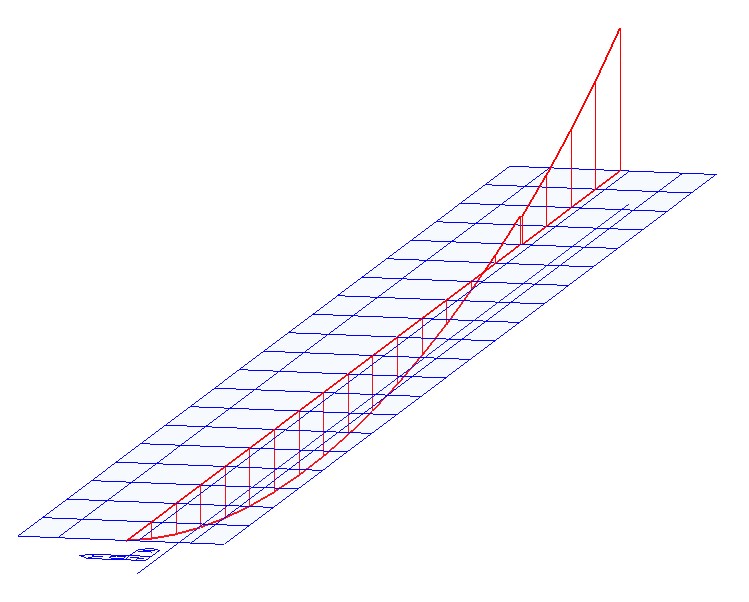
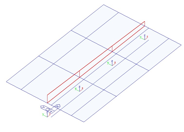
Smooth resultant force diagram when virtual section lie on the end of elements