Force & Stress Table
Check the internal forces and stresses of plate elements from the analysis results in a spreadsheet format table.
Table Tool in midas Civil offers a variety of powerful built-in functions. Refer to Usage of Table Tool for detail directions.
From the Main Menu select Results > Result Tables > Plate > Force & Stress.
From the Main Menu select Results > Result Tables > Plate > Force (Local).
From the Main Menu select Results > Result Tables > Plate > Force (Global).
From the Main Menu select Results > Result Tables > Plate > Force (Unit Length).
From the Main Menu select Results > Result Tables > Plate > Stress (Local).
From the Main Menu select Results > Result Tables > Plate > Stress (Global).
Refer to "Plate Forces/Moments", "Plane/Plate Stresses")
Upon executing the Plate > Force & Stress Table function, Records Activation Dialog prompts. Click ![]() after selecting the output entities such as nodes or elements, loading conditions, construction stages, etc.
after selecting the output entities such as nodes or elements, loading conditions, construction stages, etc.
Note
Refer to Results Table of "Usage of Table Tool" for the usage of Records Activation Dialog.
Refer to Usage of Table Tool and check the following data:
Plate Force (Local)
Elem: Element number
Load: Unit load case/combination
Stage: Construction stage
Step: Sub-stage
Node: Node number
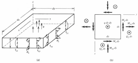
Fx: Element's internal force in the element's local x-direction
Fy: Element's internal force in the element's local y-direction
Fz: Element's internal force in the element's local z-direction
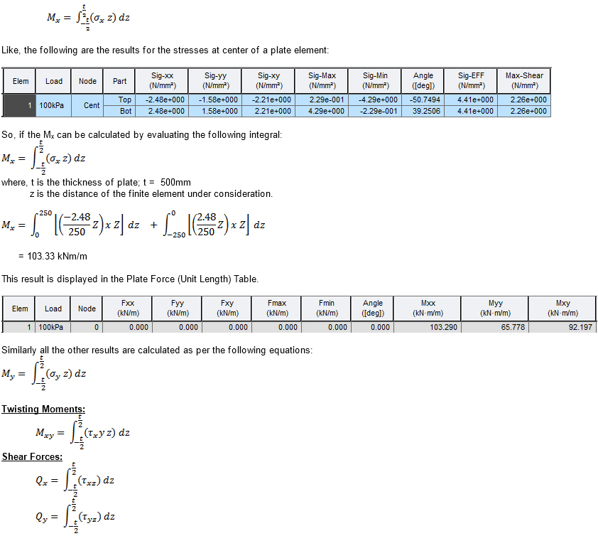
Mx: Bending moment about the element's local x-axis
My: Bending moment about the element's local y-axis
Mz: Bending moment about the element's local z-axis
Plate Force (Global)
Elem: Element number
Load: Unit load case/combination
Stage: Construction stage
Step: Sub-stage
Node: Node number
FX: Element's internal force in GCS X-direction
FY: Element's internal force in GCS Y-direction
FZ: Element's internal force in GCS Z-direction
MX: Bending moment about GCS X-axis
MY: Bending moment about GCS Y-axis
MZ: Bending moment about GCS Z-axis
Plate Force (Unit Length)
Elem: Element number
Load: Unit load case/combination
Stage: Construction stage
Step: Sub-stage
Node: Node number
Fxx: Axial force per unit width in the element's local x-direction
Fyy: Axial force per unit width in the element's local y-direction
Fxy: Shear force per unit width in the element's local x-y plane (In-plane shear)
Fmax: Maximum principal axial force per unit width
Fmin: Minimum principal axial force per unit width
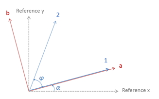
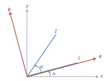
Angle: Angle formed by the element's local x-axis and the axis of the maximum principal axial force
Mxx: Bending moment per unit width relative to the element's local y-axis
Myy: Bending moment per unit width relative to the element's local x-axis
Mxy: Torsional moment per unit width about the element's local x-y axes
Mmax: Maximum principal bending moment per unit width
Mmin: Minimum principal bending moment per unit width
Angle: Angle formed by the element's local x-axis and the axis of the maximum principal bending moment
Vxx: Shear force per unit width in the thickness (z) direction on the element's local y-z plane
Vyy: Shear force per unit width in the thickness (z) direction on the element's local x-z plane
Plate Stress (Local)
Elem: Element number
Load: Unit load case/combination
Stage: Construction stage
Step: Sub-stage
Node: Node number
Part: Top or bottom fiber of a plate element in the element's local z-direction
Sig-xx: Axial stress in the element's local x-direction
Sig-yy: Axial stress in the element's local y-direction
Sig-xy: Shear stress in the element's local x-y plane (In-plane shear)
Sig-Max: Maximum principal stress
Sig-Min: Minimum principal stress
Angle: Angle formed by the element's local x-axis and the axis of the maximum principal stress vector. Angle is not generated for Envelop Type load combination since concurrent stresses cannot be calculated for the Envelop Type load combination.
Sig-EFF: Effective stress (von-Mises Stress)
Note
For the method of calculating principal stresses, effective stresses and maximum shear stresses for each load combination type, refer to the explanations at the bottom of the Combinations page.
Plate Stress (Global)
Elem: Element number
Load: Unit load case/combination
Stage: Construction stage
Step: Sub-stage
Node: Node number
Part: Top or bottom fiber of a plate element in GCS Z-direction
Sig-XX: Axial stress in GCS X-direction
Sig-YY: Axial stress in GCS Y-direction
Sig-ZZ: Axial stress in GCS Z-direction
Sig-XY: Shear stress in GCS X-Y plane
Sig-YZ: Shear stress in GCS Y-Z plane
Sig-XZ: Shear stress in GCS X-Z plane
Sig-Max: Maximum principal stress
Sig-Min: Minimum principal stress
ANG: Angle formed by GCS X-axis and the axis of the maximum principal stress vector. Angle is not generated for Envelop Type load combination since concurrent stresses cannot be calculated for the Envelop Type load combination.
Sig-EFF: Effective stress (von-Mises Stress)
Note1
The Stage and Step columns in the Analysis Result Table are produced for a construction stage analysis or Hydration Heat Analysis. The Step column is produced also for a geometric nonlinear analysis.
Note 2
For the method of calculating principal stresses, effective stresses and maximum shear stresses for each load combination type, refer to the explanations at the bottom of the Combinations page.
Wood Armer moment (Unit Length)
Elem: Element number
Load: Unit load case/combination
Stage: Construction stage
Step: Sub-stage
Node: Node number
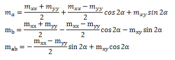
Ma: Bending moment per unit width about a-axis
Mb: Bending moment per unit width about b-axis
Mab: Twisting moment per unit width about a-b axes
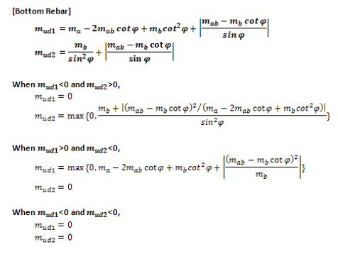
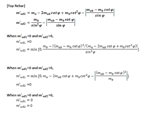
W-A Moment Top/Bot Dir1/2 : Wood Armer moment value for the respective preceding combination of moments.
Note 1. Wood-Armer formula for skew reinforcement
Note 2
Values of Ma, Mb and Mab are repeated four times in the table, because for moving load analysis, midas Civil takes into account different combinations of concurrent forces in order to achieve maximum wood armer moment for top or bottom rebar parts in any specified direction. E.g. the combination of moments to be used for maximizing “top dir-1” and “bot dir-1” moments may be quite different since the concurrent forces required to maximize these moments can be different.
![]() Revision of Civil 2014 (v2.1)
Revision of Civil 2014 (v2.1)
Q1. How can I obtain the results for Plate Force (Unit Length)?