Check Stress for Cross Section at Service Loads
Check the compression and tension stresses for cross section at service loads in a spreadsheet format table.
Table Tool in midas Civil offers a variety of powerful built-in functions. Refer to Usage of Table Tool for detail directions.
From the Main Menu select PSC > PSC Design Result Table > Check Stress for Cross Section at Service loads.
Upon executing the PSC Design Result Table > Check Stress for Cross Section at Service loads, Records Activation Dialog prompts. Click ![]() after selecting the output entities such as elements, part number, Comp./Tens. Stress.
after selecting the output entities such as elements, part number, Comp./Tens. Stress.
Refer to Usage of Table Tool and check the following data:
.jpg)
Elem: Element number
Part: Check location (I-End, J-End) of each element
Comp./Tens.: Compression or Tension Stress
LCom Name: Load Combination Name
Type: Displays the set of member forces corresponding to moving load case or settlement load case for which the maximum stresses are produced. If moving load is not defined then this field is left blank(-)
By default, member forces due to moving load case or settlement load case are not concurrent. In order to consider the concurrent member forces, namely, Fx, Fy, Fz, Mx, My and Mz each having its MAX. and MIN value, the program computes FT, FB, FTL, FBL, FTR, FBR for all these twelve sets.
For example: FT when Fx due to moving load is maximum is 30 N/mm2 and so on..
|
|
FT |
FB |
FTL |
FBL |
FTR |
FBR |
|
Fx- MAX |
30 |
40 |
25 |
35 |
35 |
30 |
|
Fx- MIN |
35 |
30 |
48 |
15 |
25 |
15 |
|
Fy- MAX |
30 |
32 |
37 |
26 |
28 |
21 |
|
Fy- MIN |
25 |
35 |
32 |
28 |
29 |
21 |
|
Fz- MAX |
18 |
15 |
19 |
14 |
15 |
10 |
|
Fz- MIN |
15 |
11 |
12 |
14 |
18 |
10 |
|
Mx- MAX |
1 |
2 |
4 |
1 |
2 |
3 |
|
Mx- MIN |
0.5 |
0.5 |
1 |
1 |
3 |
2 |
|
My- MAX |
18 |
19 |
15 |
22 |
21 |
18 |
|
My- MIN |
14 |
10 |
11 |
15 |
14 |
12 |
|
Mz- MAX |
3 |
9 |
12 |
11 |
8 |
9 |
|
Mz- MIN |
2 |
3 |
8 |
5 |
6 |
7 |
The set that results in maximum stress value FT, FB, FTL, FBL, FTR, FBR is displayed under 'Type' and the maximum stress value is displayed under FMAX. So as per above example, maximum stress value is 48, so it is displayed under FMAX, and it is from Fx-MIN set so under Type, Fx-MIN is displayed. All the values of this set will be displayed.
CHK: Combined stress check for Service loads
FT: Combined Stress due to bending moment about major axis (My) and axial force at Top fiber
FB: Combined Stress due to bending moment about major axis (My) and axial force at Bottom fiber
FTL: Combined Stress due to bending moment about major axis (My), minor axis (Mz) and axial force at Top Left fiber
FBL: Combined Stress due to bending moment about major axis (My), minor axis (Mz) and axial force at Bottom Left fiber
FTR: Combined Stress due to bending moment about major axis (My), minor axis (Mz) and axial force at Top Right fiber
FBR: Combined Stress due to bending moment about major axis (My), minor axis (Mz) and axial force at Bottom Right fiber
FMAX: Maximum combined stress out of the above six.
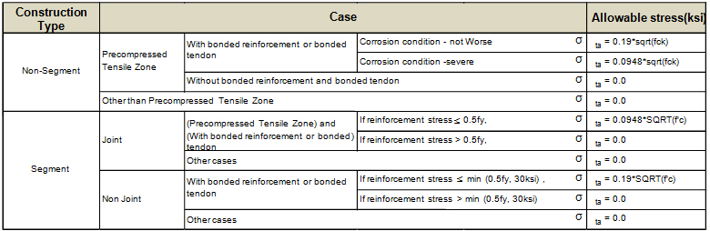
ALW: Allowable stress in concrete at service limit state as per
Note 1. Compressive stress limit for AASHTO LRFD (2012)
When AASHTO LRFD (2012) is selected, allowable compressive stress is determined based on the clause 5.9.4.2.1. Load Cases in Service Limit1 will be used to check compressive stress as specified in Concrete Allowable Stress Limit Load Case.
Compression stress limit = 0.45f'c (ksi)
Where, f’c is specified compressive strength of concrete for the use in design.
Note 2. Tensile stress limit for AASHTO LRFD (2012)
When AASHTO LRFD (2012) is selected, allowable tensile stress is determined based on the clause 5.9.4.2.2. The Load Cases in Service Limit3 will be used to check tensile stress as specified in Concrete Allowable Stress Limit Load Case.
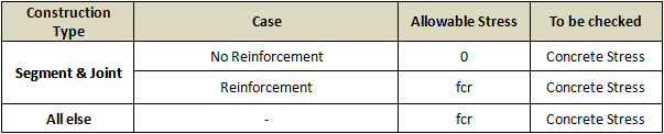
Note 3. Compressive stress limit for CSA-S6S1-2010
Allowable compressive stress of concrete at service limit is omitted in the code. midas Civil refers to the section of allowable compressive stress of concrete at construction stage in the clause 8.8.4.6 of CSA-S6S1-2010.
Compression stress limit = 0.6f'c (ksi)
Where, f’c is specified compressive strength of concrete for the use in design.
Note 4. Tensile stress limit for CSA-S6S1-2010
When CSA-S6S1-2010 is selected, allowable compressive stress is determined based on the clause 8.8.4.6.