|
Change Property
Change the property assigned to a 1D element during its creation. Select the 1D element to modify and specify the property to change.
Change Element Order
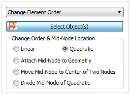
Add or delete the nodes between a 1D element to change it into a higher order or lower order element. Changing the position of the middle node to the start or end point for high order element can create an arbitrary middle node on the geometry shape. A 1D high order element can be divided into 2 low order elements with reference to the middle node.
Change Coordinate System
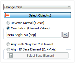
The analysis results of a structural element are printed with reference to the element coordinate axis. Hence, it is important to check the coordinate system of the structural element to make sure it is in 1 direction. Switch the element x axis direction or specify the element y axis direction to unify the major and minor axis directions of the structural elements. The direction can be unified with adjacent 2D elements.

Orientation (Element Z-axis)
This function is used to unify the direction property of a 1D element to 1 direction or to set the major and minor axis directions. Adjust the Z axis direction by checking the element coordinate axis and assign with reference to the Beta angle.
-
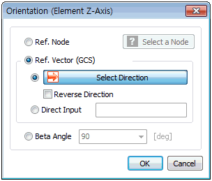
Reference Node: Select the reference node for the sectional direction of the 1D element. The element Z coordinate direction is set with reference to the selected node.
-
Reference Vector (GCS): Set the Z coordinate direction of the selected element using the GCS direction or the input vector direction.
-
Beta Angle: Angles 0, 90,180 can be chosen and the selected Beta angle rotates the element by that angle with reference to the X axis.
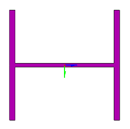 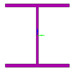 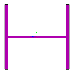
<Beta:0> <Beta:90> <Beta:180>

Add Offset (Beam/Embedded Beam)
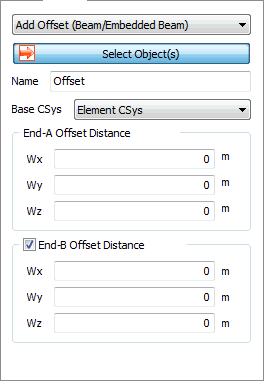
Define the offset distance by considering the sectional properties (shape) of the structural element. When defining the properties, the offset can be set within the boundary of the section shape, or outside the boundary using the extra features of offset. The offset is the eccentric distance between the position of the geometry shape (line), needed to create a structural element, and the reference axis, where the loading is applied and the results are calculated. It is mostly used to express the connection between structural members or the combined section of 2 meeting members.
Specify the reference coordinates for the offset distance calculation and input uniform or non-uniform to set the offset distance for each axial direction.
Add End Release (Beam/Embedded Beam)
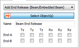
Specify the end point boundary conditions for a 1D element. It is mostly applied when specifying the connection conditions between structural members such as hinge, roller etc.
Taper Section Group (Beam/Embedded Beam)
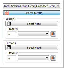 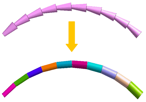
Members designated to a tapered section are grouped and calculate the section size automatically to define a constant tapered section regardless of the divided state of the elements. Firstly, select all elements that configure section changing area, and select the node at the beginning and the end of section changing area into the node of section i and j respectively. The tapered section is calculated by section property assigned to section i and j. The complex section changing area can be modeled quickly without creating the property of tapered section as the number of elements within section changing area.
|
