[Object]
For
beam elements, select the beam element directly or select
the line used to create the element to apply a load. For
continuous beam loads, the On Load Application Line Method
or Select Element Method can be used.
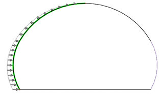
The
[On the Loading Line] command applies the load to elements
placed on the line between the two points used to specify
the continuous beam load. In this case, selecting two
nodes sequentially inputs the load for elements existing
on the line between the two points. For the [Selected
Element] command, the load is applied to the selected
element. It can be used to apply the continuous beam load
on elements that are not placed on the line. Select the
start and end points of the beam element on which the
load will be applied.
[Direction]
The
direction can be set with reference to the global coordinate
system (X,Y,Z) or element coordinate system (x,y,z). The
projected area can be additionally set, which specifies
whether to apply the load on the total beam element within
the load application section, or to apply the load by
the projected length, perpendicular to the load application
direction. This option is only valid for [Distributed]
loads in directions with respect to the global coordinate
system (GCS).
[Value
(Fraction/Length)]
x1
and x2 are the start and end points of the beam load respectively
and w1,w2 are the load size at points x1,x2. Entering
a negative load size applies the load in the opposite
direction to the set direction, and a linearly distributed
(increment, decrement) load can be set using the size
difference.
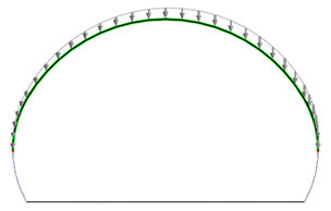 
<Apply linear beam load > |