Response Spectrum


Overview

IMG_C_ICON_DOT.gifInput the response spectrum function (spectrum data) and response spectrum load direction for response spectrum analysis. Response spectrum analysis expresses the natural period, natural angular frequency or natural frequency at the maximum physical quantity response as a function when a dynamic load is applied to the structure. The analysis can be expressed as a displacement response spectrum, pseudo rapidity response spectrum or pseudo acceleration response spectrum. The load and boundary conditions required for response analysis are similar to that of static analysis, but the load is defined as a function of time and the internal force and damping force are included for response analysis. The important results obtained from the transient response analysis are the node displacement, velocity, acceleration, and the force and stress on the element. Detailed explanations on mode combination methods and damping setting methods for maximum physical quantity (displacement, stress, member forces etc.) judgment of each mode can be found in the Analysis Control Settings.


Methodology


[Direction]

Set the application direction of the response spectrum load with respect to the global coordinate system (GSC) and input the [Period Modification Factor] that increases all applicable natural periods when applying the natural frequency from the eigenvalue analysis.


[Spectrum Function]

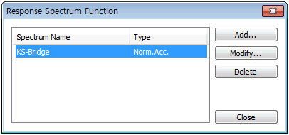
Set the spectrum data for analysis. Select the  button to define the spectrum function.


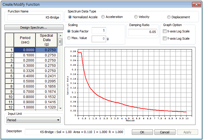
Directly input the period and spectrum value in the left input column on the dialog box. The spectrum function is expressed as a graph by plotting the spectrum value against the period. The spectrum function value for the natural period is linearly interpolated and used in response spectrum analysis. Hence, for regions where the curvature of the spectrum curve changes rapidly, dividing the region into multiple segments for compact spectrum values is recommended. The period range of the spectrum function must contain all natural periods of the structure.

The spectrum data types are normalized acceleration (acceleration spectrum, gravitational acceleration), acceleration, velocity and displacement spectrum. Changing the time function data format only changes the application format, not the data format. The scale factor is a gradient modulus for the entered data. The entire data can be scaled to fit the specified maximum value.

In the [Damping Ratio] space, input the damping ratio applied on the response spectrum. But if the damping ratio of the target structure is different, the input spectrum data is processed to fit the structural damping ratio.

IMG_C_ICON_NOTE_01.png

Apply Design spectrum

Use the built-in design spectrum. The default built-in design spectrum types are as follows.


  • Korea(Bridge) : Korea, Traffic Specification

  • Japan(Bridge02) : Japan, Load instruction and Dynamic Analysis of Building

  • China(JTJ004-89) : China, Specifications of Earthquake Resistant Design for Highway Engineering

  • KBC 2009 : Korea, Korea Building Code-Structural 2009

  • KBC 2005 : Korea, Korea Building Code-Structural 2005

  • IBC2000(ASCE7-98) : USA, International Building Code 2000

  • UBC(1997) : USA, Measure of Uniform Building Code 97

  • EURO(2004H-ELASTIC) : Europe, Sesimic Design Measure for Structures