|
 Show/Hide grid Show/Hide grid
Show or hide the grid on the screen.
 Show/Hide Datum Axis/Plane Show/Hide Datum Axis/Plane
Show or hide the datum axis/plane on the screen.
 Show/Hide WCS Show/Hide WCS
Show or hide the WCS on the screen.
The WCS (Work-plane Coordinate System) is the coordinate system of the work-plane. Work-plane is user-defined plane to facilitate modeling
 Show/Hide GCS Show/Hide GCS
Show or hide the GCS on the screen.
The GCS (Global Coordinate System) is the fixed global coordinate system.

There are two basic coordinate systems used in the GTX NX; The Global Coordinate System (GCS) and the Work-plane Coordinate System (WCS).
The GCS (Global Coordinate System) is the fixed global coordinate system expressed in the bottom right-hand corner using red (X-axis), green (Y-axis) and blue (Z-axis) arrows.
The WCS (Work-plane Coordinate System) is the coordinate system that moves with the work-plane and can be found at the center of the work screen. Because the work-plane is used for entering the 2-dimensional coordinates of a shape, the WCS changes along with the workplace. The absolute 3-dimensional coordinates are necessary to create a shape in space, but in most cases the only the relative coordinates such as the model length are given. In this case, modeling can be done easily by moving the work-plane to an appropriate position and then entering the 2-dimensional coordinates (the XY plane on the WCS).
Please note that when extruding the geometric shape, the load/boundary conditions and extrude direction follows the GCS.
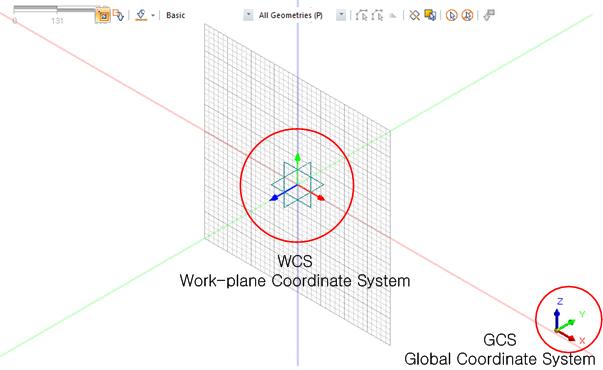
<Global Coordinate System(GCS) and Work-plane Coordinate System(WCS)>

 Move work plane Move work plane
Move the work-plane to the desired location. This can be done by [Reference plane], [3 point plane] or [Normal direction] methods.
This function moves the current work-plane to the desired location. This can be done by [Reference plane], [3 point plane] or [Normal direction] methods.
-
[Reference plane]: This function moves the grid to a plane parallel to the reference plane. Clicking the [Normal ] after moving the grid helps the user work more easily. This function is convenient when working on a plane different from the specified work-plane.
FEA NX provides 7 basic work-planes: XY(0,0,1), XZ(0,-1,0), XZ(0,1,0), YX(0,0,1), YZ(1,0,0), ZX(0,1,0), ZY(1,0,0).
If the workspace is a certain distance from the plane, the user can specify the grid origin using the [Offset] function.
-
[3 point plane]: This function moves the work-plane by selecting 3 points. The work-plane moves to the plane define by the selected points, with the vector created by the first and second points the X-axis and the vector created by the first and third points the Y-axis.
-
[Normal direction]: This function moves the work-plane by selecting a vector and a reference point. The reference point is defined as the origin and the normal direction to the vector is defined as the vertical axis.
[Reverse Normal]
Reverse the vertical direction (the Z-axis of the WCS) of the plane.
[Reset to GCS]
Return to the initial grid position.
[Save]
Check the [Save] button and enter a name to register the workplace under Work tree > Workplane.
 Define grid Define grid
The grid is always located on the XY plane of the work-plane to ease the modeling process. When modeling with the grid, the grid snap ( ) function can be used to specify the desired location and easily estimate the approximate model or element sizes. ) function can be used to specify the desired location and easily estimate the approximate model or element sizes.
The grid setting can be set according to the convenience of the user and the dimensions of the model.
 Define snap Define snap
The user can specify the location of the point using various snap options shown in the table below.
|
Grid snap
|
Positions the mouse snap on a grid point in the work-plane.
|
|
Point snap
|
Positions the mouse snap on a point.
|
|
End snap
|
Positions the mouse snap on the closest endpoint of an edge.
|
|
Middle snap
|
Positions the mouse snap on the midpoint of an edge.
|
|
Perpendicular snap
|
Positions the mouse snap on the perpendicular point of an edge.
|
|
Center snap
|
Positions the mouse snap on the center point of a circle/arc.
|
|
Quadrant snap
|
Positions the mouse snap on the four circle/arc quadrant points.
|
|
Intersection snap
|
Positions the mouse snap on the intersection point between two edges.
|
|
Tangent snap
|
Positions the mouse snap on the tangent point.
|
|
Arbitrary snap
|
Designates an arbitrary snap.
|
|
Node
|
Positions the mouse snap on a node.
|
When using a snap related to a particular edge, such as end snap or middle snap, the user needs to position the mouse above the target edge of the snap, rather than on the position of the target (end, middle).
|