|
Cutting DiagramThe diagram setting method can be specified as [Line] or [Surface], and the results can be displayed as a diagram.
Cutting Line
-
Select a 2-point line or edge when defining the position.
-
For the 2-point line, select the coordinates directly on the screen or input the coordinates of the 2 points.
-
Then, specify the direction of the diagram and input the number of samples to divide the diagram by that number and display on the screen.
-
The diagram direction follows the GCS and the default direction is the (+) direction. To draw the diagram in the opposite direction, check the [Reverse] option. For the edge, select [Only On Node] to draw the diagram on that node position. Only one edge can be selected.
-
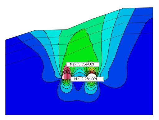
The arbitrary line diagram is useful when assessing the relative settlement conditions of a geotechnical structure for 2D models.
Cutting Plane
-
Select a 3-point face or plane when defining the position.
-
For the 3-point face, select the coordinates directly on the screen or input the coordinates of the three points.
-
The diagram direction can be selected in the [Plane Surface] or [Plane Normal] direction, and the [Reverse] option can be checked to draw the diagram in the opposite direction.
-
The sample number is the number of diagram divisions displayed on the screen.
-
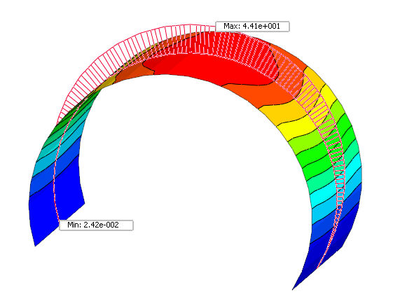
The arbitrary plane diagram is useful when checking the member force distribution in a particular section of a 3D model(ex. Lining transitional section model).
|