Moment Curvature Curve
Display the moment-curvature relationship to consider the inelastic capacity of the generated cross-section.
Moment-curvature curve is calculated based on the nonlinear material properties defined in the Material Data dialog box. If the nonlinear material is not defined, the moment-curvature curve will be calculated based on the rectangular stress distribution for concrete from Eurocode2-1-1:2004 clause 3.1.7 and the bilinear stress-strain relationship for rebar and steel.
From the Main Menu select Results > Moment Curvature Curve.
Click ![]() Moment
Curvature Curve in the Icon Menu.
Moment
Curvature Curve in the Icon Menu.
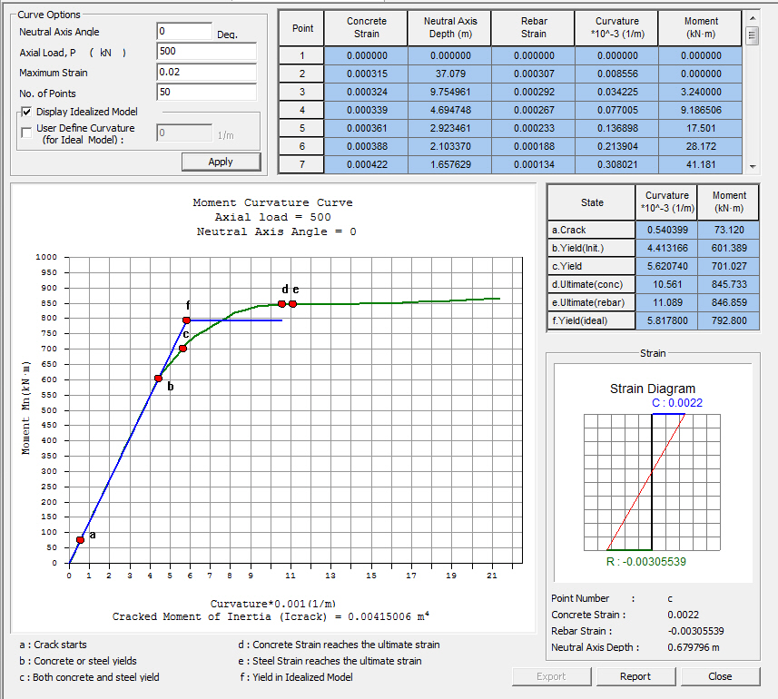
Moment-Curvature Curve dialog box
![]() Curve Options
Curve Options
Neutral Axis Angle: Enter the angle of neutral axis for which moment-curvature curve is calculated.
Axial Load, P: Enter the initial axial force.
Maximum Strain: Enter the ultimate strain value of the summation between Comp. Strain and Tens. Strain.
No. of Points: Number of points to plot moment-curvature curve
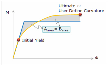
Display Idealized Model : Generate the idealized bilinear moment-curvature curve. In the figure below, the yellow line represents the moment curvature curve and blue line represents the idealized curve. The idealized curve is generated to have the same area between Aarea and Barea after passing the initial yield point.
User Define Curvature (for Ideal Model) : Generate the idealized model up to the specified curvature. If it is not specified, the idealized curve is generated by “point d. ultimate (concrete)” for which the concrete strain reaches its ultimate strain.
![]() Moment-Curvature Table
Moment-Curvature Table
Steel Comp. Strain: Structural steel strain at the extreme compression fiber
Concrete Strain: Concrete strain at the extreme compression fiber
Neutral Axis Depth: Distance from the neutral axis to the extreme compression fiber
Steel Tens. Strain: Structural steel strain in the extreme tension fiber
Rebar Strain: Maximum reinforcement strain among the reinforcements in tension
Curvature: Rotation per unit length of member (Curvature, phi = (compressive strain + tension strain) / effective depth)
Moment: Bending moment of the cross-section
![]() Moment-Curvature
for Crack, Yield, and Ultimate Point
Moment-Curvature
for Crack, Yield, and Ultimate Point
Crack : Display the values at the time when the concrete starts cracking.
Yield(Initial) : Display the values at the time when either concrete or steel yields. The yield criteria of concrete and steel are defined in the Nonlinear Properties of the Material Data dialog box.
Yield : Display the values at the time when both concrete and steel yield. The yield criteria of concrete and steel are defined in the Nonlinear Properties of the Material Data dialog box.
Note
The values above may not be defined depending on the types of hysteresis curves. In such case, ”0” will be displayed.
Ultimate(Conc) : Display the values at the time when concrete strain reaches its ultimate strain.
Ultimate(Rebar) : Display the values at the time when rebar strain reaches its ultimate strain.
Note
The Ultimate strain is defined in the Nonlinear Properties of the Material Data dialog box. If the nonlinear material properties are not defined, ultimate strain is determined based on the entered value in the Maximum Strain field.
Yield(Ideal) : Display the values at the yield point of an idealized model.
![]() Strain
Diagram
Strain
Diagram
Strain diagram is displayed for each point. It is updated based on the mouse curser position on the Moment-Curvature graph in real time.
![]() Export
Export
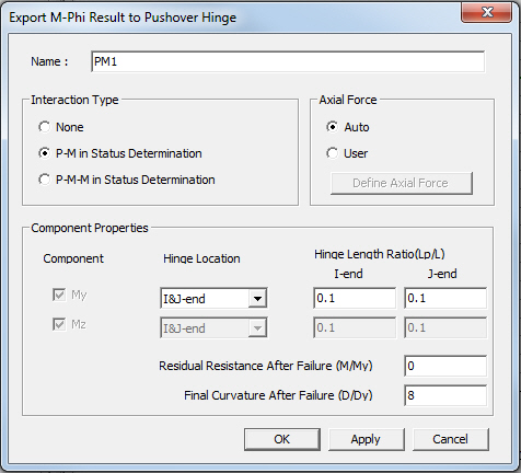
Export M-Phi Results to Pushover Hinge dialog box
Pushover hinge properties in midas Civil/Gen can be automatically generated using the idealized model of Moment-Curvature Curve.
Note
- Definition type of pushover hinge in midas Civil/Gen is defined as Moment-Curvature (M-Phi Lumped) type.
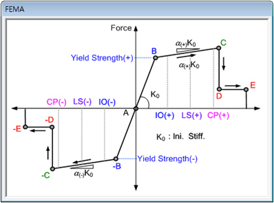
- Skeleton Curve Type is defined as FEMA.
Name : Enter the name of pushover hinge property.
Interaction Type
None : Axial force and biaxial moments are uncoupled from each other.
P-M in Status Determination: Coupled axial force-uniaxial moment behavior is reflected by calculating the flexural yield strength of a hinge considering the effect of axial force.
P-M-M in Status Determination: Coupled axial force-biaxial moment behavior is reflected by calculating the flexural yield strength of a hinge considering the effect of axial force.
Axial Force : Define the axial force in order to export the multiple moment-curvature curves by various axial forces.
Auto : Axial forces are automatically defined by the program.
User : Axial forces are defined by the user.
Note
- When “Auto” option is selected for Axial Force, the program automatically generate M-Phi curve with the axial forces in the 4th, 7th, 9th, 11th, 13th, 15th, 17th, 19th, and 22nd rows from the Moment-Curvature Table.
- When Interaction Type is selected as None, M-Phi curve is exported with zero axial force.
Component Properties
Component : Check on the degree of freedom to be assigned to the plastic hinge type.
Hinge Location : Select the hinge location of M-Phi Lumped type hinge.
Hinge Length Ratio(Lp/L): Enter the ratio of hinge length. The value cannot exceed “0.5”.
Residual Resistance After Failure (M/My) : Enter the moment ratio(M/My) at the point D in the figure below.
Final Curvature After Failure (D/Dy) : Enter the curvature ratio (D/Dy) at the point D in the figure below.
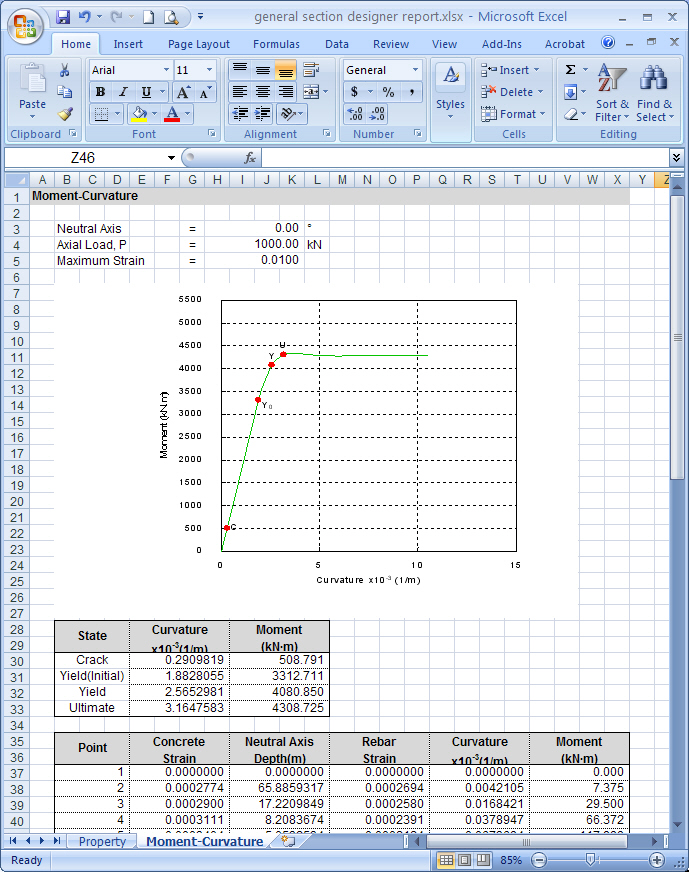
![]() Report
Report
Click
![]() to generate the report
in Microsoft Excel format. The generated excel file is saved in
the same folder as the one that the *.mgs model file has been
saved.
to generate the report
in Microsoft Excel format. The generated excel file is saved in
the same folder as the one that the *.mgs model file has been
saved.