Revision of Ver.7.4.1 Revision of Ver.7.4.1
Function
Enter spring stiffness per unit supporting area of planar or solid elements to create elastic spring supports. Elastic Link elements may be created simultaneously. This function is mainly used to define a number of elastic supports on surfaces represented by the modulus of spring. For example, if the user wishes to define elastic supports for subgrades of foundations or underground structures, subgrade springs will be automatically entered at each node represented by concentrated stiffness. This function enable the user to specify the surface or line stiffness without having to worry about the discretization (sizes) of elements, which is automatically taken care of by the program.
Call
From the Main Menu select Model > Boundaries > Surface Spring Supports.
Select Geometry > Boundaries > Surface Spring Supports in the Menu tab of the Tree Menu.
Entry
Click  to the right of Surface Spring Supports: Display the
Surface Spring Supports Table
to the right of Surface Spring Supports: Display the
Surface Spring Supports Table
Note
The data entered in Surface Spring Supports
are converted into Point Spring
Supports or Elastic Link
data and saved as such.
Revision of Ver.7.4.1|
|
|
 When Point Spring
is selected
When Point Spring
is selected
|
|
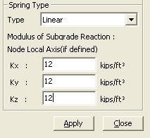
• Spring Type : Linear Modulus of Subgrade Reaction: Subgrade stiffness Kx: Stiffness per unit area in the node's local x- direction (GCS X-direction) Ky: Stiffness per unit area in the node's local y- direction (GCS Y-direction) Kz: Stiffness per unit area in the node's local z- direction (GCS Z-direction)
|
|
|
• Spring Type : Compression / Tension Direction: Direction of the Point Spring Normal(+): Normal (+ dir) to the surface (average normal direction of surfaces connected to the node defined with Point Spring) Normal(-): Normal (- dir) to the surface (average normal direction of surfaces connected to the node defined with Point Spring) Note The normal direction of planar elements is defined by the right hand rule based on the node entry sequence. For solid elements, the normal direction (+) is oriented away from the surfaces of the elements. UCS-x(+): UCS +x-direction (GCS +X-direction) UCS-x(-): UCS -x-direction (GCS -X-direction) UCS-y(+): UCS +y-direction (GCS +Y-direction) UCS-y(-): UCS -y-direction (GCS -Y-direction) UCS-z(+): UCS +z-direction (GCS +Z-direction) UCS-z(-): UCS -z-direction (GCS -Z-direction) Modulus of Subgrade Reaction: Subgrade stiffness
|
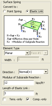
When Elastic
Link is selected
|
|
Direction: Direction of the elastic link Normal(+): Normal direction of the surface (average normal direction of surfaces connected to the node defined with Elastic Link) Normal(-): Normal direction of the surface (average normal direction of surfaces connected to the node defined with Elastic Link) Note UCS-x(+): UCS +x-direction (GCS +X-direction) UCS-x(-): UCS -x-direction (GCS -X-direction) UCS-y(+): UCS +y-direction (GCS +Y-direction) UCS-y(-): UCS -y-direction (GCS -Y-direction) UCS-z(+): UCS +z-direction (GCS +Z-direction) UCS-z(-): UCS -z-direction (GCS -Z-direction) Modulus of Subgrade Reaction: Subgrade stiffness Length of Elastic Link: Length of elastic link element. The length dose not affect the analysis. It is simply required to define a vector internally in the solver. Tens. Only, Comp.-Only: Check in an option to assign elastic link with tension-only or compression-only elements
|
.jpg)
 Boundary Group Name