.jpg) be
used to auto-generate the data necessary for the stories and the application
of wind loading. Where openings exist at a particular story, adjust the
width of the wind pressure area.
be
used to auto-generate the data necessary for the stories and the application
of wind loading. Where openings exist at a particular story, adjust the
width of the wind pressure area.Function
In MIDAS/Gen, the automatic data entry of wind loads according to various standards is applicable for common buildings where each story can be defined and can reasonably act as a rigid diaphragm. The following procedure is observed :
Model the structure.
The structure must be modeled so that the gravity acts in the direction opposite to the GCS Z-direction.
Use Building > Control Data to define the elevation of ground level in GCS Z-axis coordinate.
When the ground level is entered, the parts below this level are considered as underground stories and neglected in the wind load calculation. If the ground level is not specified, the lowest part of the modeled structure is assumed to be the ground level by default.
Use Story to define stories and their floor rigid diaphragm characteristics. Enter the application position of wind loads and the width of the story subjected to pressure to generate the wind load at each story.
It is recommended that be
used to auto-generate the data necessary for the stories and the application
of wind loading. Where openings exist at a particular story, adjust the
width of the wind pressure area.
Once the floor diaphragm is defined in Story, the X-, Y-displacement degrees-of-freedom and the rotational degree-of-freedom about the Z-axis between all the nodes on the plane (plane parallel to the GCS X-Y plane) are constrained.
In addition, a part or all of the constrained nodes can be separated from the rigid floor diaphragm using Floor Diaphragm Disconnect.
Assign the wind load calculation standards in Wind Loads and enter the required data. The built-in wind load calculation standards in MIDAS/Gen are as follows:
IBC 2000 (ASCE7-98): International Building Code 2000
UBC (1997): UBC 97 standards
ANSI (1982): ANSI standards
NBC (1995): National Building Code of Canada
Eurocode-1 (1992): Basis of Design and Actions on Structures
BS6399 (1997): British Standard 6399 Loading for buildings
IS875(1987): Indian Standard
Taiwan (2002): Taiwan Building Code
(available upon request)
Japan (Arch, 2004): Loading Specifications and Commentaries for Buildings
Japan (Arch, 2000): Loading Specifications and Commentaries for Buildings
Japan (1987): Loading Specifications and Commentaries for Buildings
Korean (Arch, 2000): Buildings loading criteria and commentaries
Korean (Arch, 1992): Regulations related to structural criteria for buildings
China (GS50011-2001): Code for Seismic Design of Building
Once the data required for the calculation
of wind loads are defined, auto-calculate wind loads for each story in
connection with the story data generated in Story. Use .jpg) to
verify the auto-calculated wind loads.
to
verify the auto-calculated wind loads.
.jpg)
1) Wind load calculation
If a floor area changes at a particular story level, the area subject to wind pressure is based on the sum of (A1=B1*h1/2) and (A2=B2*h2/2) relative to the corresponding story level.
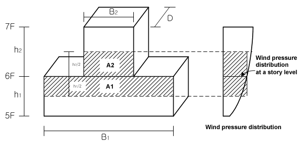
Fig. 2 Elevation
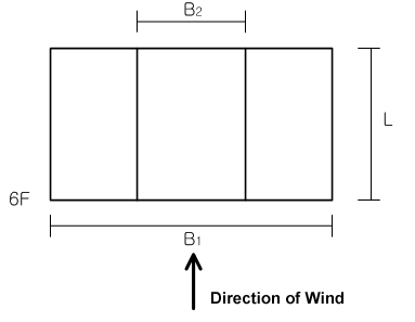
Fig. 3 Plan
2) External Pressure Coefficient
Based on L/B2 for the upper portion and L/B1 for the lower portion
3) Design Pressure
Actual distribution of the wind pressure is parabolic, but MIDAS/Gen expresses it in a stepped distribution because the design pressure is taken at the story levels as per Fig. 2.
Call
From the Main Menu select Load > Wind Loads.
Select Static Loads > Wind Loads in the Menu tab of the Tree Menu.
Usage
Access Wind Loads to activate the dialog
box defining the wind loads. Click .jpg) to display the dialog
box shown below.
to display the dialog
box shown below.
 Load Case Name
Select the load case name to be associated
with the wind load. Click .jpg) to the right to enter or modify
new load cases.
to the right to enter or modify
new load cases.
Wind Load CodeSelect the standards to be applied to the wind load calculation.
IBC 2000(ASCE7-98): International Building Code 2000
UBC (1997): UBC 97 standards
ANSI (1982): ANSI standards
NBC (1995): National Building Code of Canada
Eurocode-1 (1992): Basis of Design and Actions on Structures
BS6399 (1997): British Standard 6399 Loading for buildings
IS875 (1987): Indian Standard
Taiwan (2002): Taiwan Building Code
DescriptionEnter a short description.
Wind Load ParametersEnter the parameters to be applied to the wind load calculation.
IBC 2000(ASCE7-98)
Simplied Procedure
Basic Wind Speed
Importance Factor
Exposure Category
Analytical Procedure
Basic Wind Speed
Wind Directionality Factor
Important Factor
Exposure Category
Mean Roof Height
Gust Effect Factor
Gust Factor Parameter
X-Breadth (Bx)
Y-Breadth (By)
X-Natural Frequency
Y-Natural Frequency
Damping Ratio
.jpg) : Calculate
Gust Factors
: Calculate
Gust Factors
Gust Factor X
Gust Factor Y
Load Evaluation Using Force Coefficient : Determine whether to calculate load using wind force coefficient.
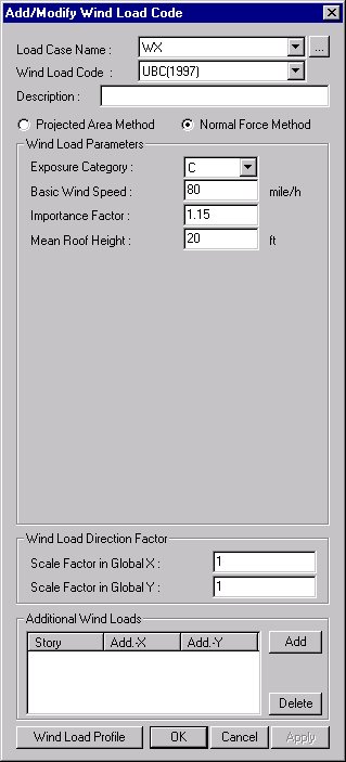
UBC (1997)
Projected Area Method
Exposure Category
Basic Wind Speed
Importance Factor
Pressure Coefficient
Normal Force Method
Exposure Category
Basic Wind Speed
Importance Factor
Mean Roof Height
ANSI (1982)
Exposure Category
Basic Wind Speed
Importance Factor
Windward Coefficient: Windward wind pressure coefficient
Leeward Coefficient: Leeward wind pressure coefficient
NBC (1995)
Simple Procedure
Reference Wind Speed
Gust Effect Factor
Detailed Procedure
Reference Wind Speed
Gust Effect Factor
X-Breadth (Wx)
Y-Breadth (Wy)
X-Natural Frequency(Nox)
Y-Natural Frequency(Noy)
Damping Ratio
Building Height
Exposure Category
Include Topography Effect
Hill Shape
2-D Ridge or Valley
2-D Escarpment
3-D Axisym. Hill: 3-dimention axisymmetrical hills
Building Location: Building Location in case 2-D Escarpment
Upwind
Downwind
Hill Height: Height of the hill or the difference in elevation between the crest of the hill and that of the terrain surrounding the upstream
Hill Length: Distance upwind of the crest to where the ground elevation is half the height of the hill
Crest-Building Distance (x): Distance from crest to the building site
Load Evaluation Using Force Coefficient: Determine whether to calculate load using wind force coefficient.
Eurocode-1 (2005)
Terrain Category: Exposure category
Friction Coefficient (Cfr)
Fund. Basic Wind Velocity (Vb,o)
Directional Factor (Cdir)
Seasonal Factor (Cseason)
Turbulence Factor (KI)
Building Height (h): Automatically inputted by the program
External Pressure Coefficients
Windward(A=10): Windward wind pressure coefficient for the area of 10m2
Windward(A=1): Windward wind pressure coefficient for the area of 1m2
Leeward Coef.: Leeward wind pressure coefficient
Lack of Correlation Factor: Lack of correlation of wind pressures between the windward and leeward sides
Parameters for Mean Wind Velocity
Consider Orographic Effects: Consider the increase of wind velocities over orography.
Orography Type
Building Location
Height of Topographic Feature
Length of Upwind Slope
Length of Downwind Slope
Crest-Building Distance: Distance from crest to the building site
Consider Effects of Neighbouring High-rise Structures: Consider the influence of higher neighboring structures on the wind velocities.
Building Height: Automatically inputted by the program
Average Height of Nearby Structures
Distance to the High-rise Structure: Distance from the building site to the neighboring high-rise building
Larger Horizontal Dimension: Larger horizontal dimension of the neighboring high-rise building
Height: Height of the neighboring high-rise building
Consider Raising of Displacement Height: For buildings in Terrain Category IV, closely spaced buildings and other obstructions causes the reduction in wind velocities.
Obstruction Height: Height of the neighboring structure or the obstruction
Upwind Spacing: Distance to the neighboring structure or the obstruction
Structural Factor: Gust effect factor
Along Wind Breadth
Along Wind Depth
Along Wind Natural Frequency
Logarithmic Decrement of Damping
Load Evaluation Using Force Coefficient: Calculate load using wind force coefficient
Force Coefficient
Eurocode-1 (1992)
Simplified Procedure
Roughness Category
Ref. Wind Speed (Vref)
Windward Pressure Coef.
Leeward Pressure Coef.
Friction Coef.(Cfr)
Topography Coef. at Building Ground Level Ct
Vertical Range for Ct
Force Coefficient (Cf)
Detailed Procedure
Roughness Category
Ref. Wind Speed (Vref)
Windward Pressure Coef.
Leeward Pressure Coef.
Friction Coef.(Cfr)
Topography Coef. at Building Ground Level Ct
Vertical Range for Ct
Gust Response Factor
: Gust Response Factor Calculator
Building Height (H)
Along Wind Breadth (B)
Along Wind Depth (D)
Along Wind Natural Freq (NI)
Fund. Flex. Damping (delta)
: Calculate
Gust Response Factors
Force Coefficient (Cf)
BS6399 (1997)
Standard Method
Site Category
Building Type Factor (Kb)
Basic Wind Speed (Vb)
Mean Roof Height (Ho)
Seperation of Building (X)
Friction Drag Coef. (Cf)
Closet Diatance to Sea
Directional Method
Distance to Town Edge (Sa)
.jpg)
Altitude Factor (Sa)
Directional Factor (Sd)
Seasonal Factor (Ss)
Probability Factor (Sp)
Topographic Increment (Sh)
IS875 (1987)
Standard Method
Basic Wind Speed
Terrain Category
Building Class
Friction Drag Coef.(Cf')
Risk Coefficient
Class of Structures
Risk Coefficient (k1)
Include Topographic Effects
Topographic Factor (k3)
Vertical Range for k3
Taiwan (2002)
Site Category
Shape Factor
Wind Load Direction FactorEnter the loading direction and the magnitude of wind load to be applied.
Scale Factor in Global X: Scale factor to be applied in GCS X-direction
Scale Factor in Global Y: Scale factor to be applied in GCS Y-direction
Z-Rot: Scale factor to be applied in torsion about GCS Z-direction
Note
It is activated only when Japan (Arch, 2004) is selected.
Additional Wind LoadsEnter additional wind loads that the auto-calculation does not take into account.
Press .jpg) to enter the stories
to apply additional wind loads and the magnitudes for each direction.
to enter the stories
to apply additional wind loads and the magnitudes for each direction.
: Display Tables and Graphs
in a spreadsheet form for each loading direction and component of the
auto-calculated wind loads.
Component: Assign the wind loading direction for a graphic display
Select Profile: Select the items to be displayed
Story Force
Story Shear
Overturning Moment
.jpg) : Display a spreadsheet Text
Output file showing the wind load calculation process. Text Editor is
automatically executed.
: Display a spreadsheet Text
Output file showing the wind load calculation process. Text Editor is
automatically executed.
.jpg) : Apply the auto-calculated
wind loads to the model.
: Apply the auto-calculated
wind loads to the model.
Note
Refer to the relevant code for details regarding
the wind load calculation.