|
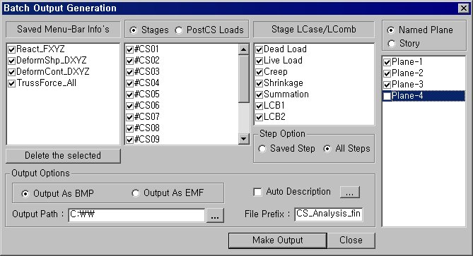
Specify the Base Files to perform Batch Output Generation, planes, etc
in the following dialog box.
Saved
Menu-Bar Info's: Listed here are the Base Files. Select the Base
File Names for Batch Output.
 : Delete all the Base Files selected with the mouse. : Delete all the Base Files selected with the mouse.
When the construction stage analysis is
carried out, all the construction stages are listed. We simply select
the stages of interests to be included in the batch output. If no construction
stage analysis is performed, the column in the dialog box becomes inactive
and lists load (combination) conditions.
Stages
The results output of all the construction
stages are produced. The construction stages are listed below.
PostCS Loads
The results output for only the Final Stage
are produced. The construction stages are listed below. If no construction
stage analysis is performed, the load (combination) conditions are listed.
Use Saved
Apply only the (saved) step or load (combination)
condition selected at the time of creating each Base File.
Stage LCase/LComb
When the construction stage analysis is
carried out, the auto-generated construction stage load conditions and
the additionally entered construction stage load combinations are listed.
Check on only the load (combination) conditions that will be used to produce
batch outputs. This column becomes inactive if “Final Stage Loads?is selected
or no construction stage analysis is carried out.
Step Option
Specify the steps for which the outputs
will be produced when the construction stage analysis or large displacement
geometric nonlinear analysis is performed.
Saved Step:
Use only the steps used for creating the Base Files
All Steps:
Use all the steps
Named Plane: Select Planes that
will be used to produce batch graphic output.
Story: Specify Stories that
will be used to produce batch graphic output.
Output Options
Output As BMP
Select a Graphic File type as BMP.
Output As EMF
Select a Graphic File type as EMF.
Auto Description: At the top
left of the Graphic Outputs produced in batch, auto-generate and include
the notes such as the types and components of the analysis results, construction
stages and steps, load (combination) conditions, etc. The font size, color,
type, etc. can be changed upon clicking the button .
Output Path
Specify the path for saving the graphic files to be produced in batch.
File Prefix: Specify the prefix
of the Graphic Files to be created. The filenames will be consisted of
"Prefix"_"Base File Name"_"Load Comb.".bmp(emf)
or "Prefix"_"Base File Name"_"Stage"_"Stage
LCase"_"Step".bmp(emf).
 : Produce the specified batch Graphic Files reflecting the
contents of the dialog box. : Produce the specified batch Graphic Files reflecting the
contents of the dialog box.
 / / 
Produce the contents of data input in the Base Files and Batch Output
Generation dialog box in a binary type file (fn.bog). Click the button
and select a fn.bog to use the same output format.
Note
Import /Export is only meaningful for different
projects. In a given structural model, the Base Files are automatically
stored and listed. | 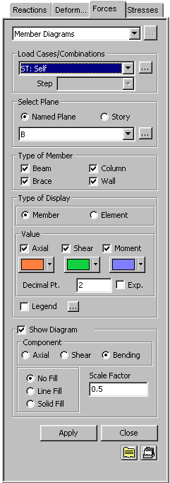
 Load Cases/Combinations
 to the right of Load Cases/Combinations in the dialog box
to add new or modify or delete existing load combinations. (Refer to "Load Cases / Combinations")
to the right of Load Cases/Combinations in the dialog box
to add new or modify or delete existing load combinations. (Refer to "Load Cases / Combinations")

.jpg) ,
, .jpg) )
)