 Option
Function
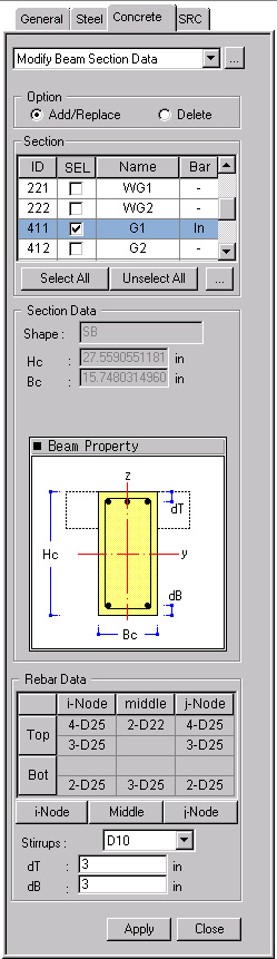
Enter the section dimensions and rebar data for RC beam members for strength verification.
Call
From the Main Menu select Design > Concrete Design Parameter > Modify Beam Section Data.
From the Menu tab of the Tree Menu select Design > Concrete Design Parameter > Modify Beam Section Data.
Entry
First, select the members in the model and enter the following data:
OptionSelect Add/Replace or Delete.
Add/Replace: Add the newly entered values or update the previously entered values.
Delete: Delete the entered values. Data entry is not required when deleting.
|
|
Select the sections for which strengths will be checked. ID : Section Number SEL: Check on to select the members for which section changes are made and rechecked and the results are produced. Note: Use SpaceBar Key to select or cancel. Name : Section Name Bar: Status of rebar placement (In: rebars are placed, -: rebars are not placed)
Click
Display the section data for beam members. Shape: Sectional shape of the members Hc: Height of the section Bc: Width of the section bf: Width of the T-section's flange hf: Thickness of the T-section's flange
|
Rebar DataEnter the reinforcing data at each position of the beam section for strength verification.
.jpg) : Enter/modify rebar data
at node i of the beam members. The following Definition of Beam Rebar
dialog box is displayed:
: Enter/modify rebar data
at node i of the beam members. The following Definition of Beam Rebar
dialog box is displayed:
.jpg)
Top Rebar
Enter the top rebar data.
One Layer: Rebar placement in one layer
Two Layers: Rebar placement in two layers
 : Number of top rebars
in the upper layer
: Number of top rebars
in the upper layer
 : Number of top rebars
in the lower layer
: Number of top rebars
in the lower layer
 : Rebar size
Bottom Rebar
Enter the bottom rebar data.
One Layer: Rebar placement in one layer
Two Layers: Rebar placement in two layers
 : Number of bottom rebars
in the upper layer
: Number of bottom rebars
in the upper layer
 : Number of bottom rebars
in the lower layer
: Number of bottom rebars
in the lower layer
 : Rebar size
Stirrup Bar Space: Spacing of stirrup bars
.jpg) : Enter the values or
the selection and close the dialog box.
: Enter the values or
the selection and close the dialog box.
.jpg) : Do not enter the values
or the selection and close the dialog box.
: Do not enter the values
or the selection and close the dialog box.
.jpg) : Enter the reinforcing data
pertaining to (1/4)L, (1/2)L and (3/4)L positions of the beam members.
Data entry is identical to that for i-Node.
: Enter the reinforcing data
pertaining to (1/4)L, (1/2)L and (3/4)L positions of the beam members.
Data entry is identical to that for i-Node.
.jpg) : Enter/Modify the reinforcing
data at node j of the beam members. Data entry is identical to that for
i-Node.
: Enter/Modify the reinforcing
data at node j of the beam members. Data entry is identical to that for
i-Node.
Stirrup Bar : Spacing of stirrup bars
Arrangement: Number of shear reinforcement legs
dT : Distance between the center of the top main rebars in the upper layer and the top surface of the section (cover thickness) (refer to Note 3)
dB : Distance between the center of the bottom main rebars in the lower layer and the bottom surface of the section (cover thickness) (refer to Note 3)
.jpg) : Enter the values for
the selected members.
: Enter the values for
the selected members.
.jpg) : Close the entry Dialog
Bar.
: Close the entry Dialog
Bar.
Note
1
The dimensions entered for the analysis model determine the height (Hc)
and width (Bc) of the rectangular section (Shape = Rectangle). In such
a case, the sectional shape of the beam members defined in the analysis
model must be rectangular. The sectional values (Hc, Bc, bf, hf) entered
in the analysis model are applied to T-sections (Shape = Tee). In such
a case, the sectional shape of the beam members entered in the analysis
model must be a T-shape. Use "Section for Design" to modify
the sectional shape or the dimensions (refer to "Section
for Design").
Call
From the Main Menu select Design > Section for Design
Note
2
The rebar data dialog box for a
"Tee"-section is as follows:
.jpg)
Note
3
Enter the cover dimensions of the main rebars placed in the outer layers
of the beam members. When the covers are not specified, (dT = 0, dB =
0), strength verification will not proceed.
Note
4
Rebar data at only one section among the locations of i-Node, Middle and
j-Node may be entered. If there are no rebar data, the strength will not
be verified.
When rebar data are entered for only one of the i-Node, j-Node and Middle locations: The rebar data will be applied to all the locations for strength verification.
When rebar data are entered for i-Node and j-Node: The i-Node rebar data will be used for the Middle for strength verification.
When rebar data are entered for i-Node and Middle: The i-Node rebar data will be used for j-Node for strength verification.
When rebar data are entered for Middle and j-Node: The j-Node rebar data will be used for i-Node for strength verification.
Note
5
When the rebar data are repeatedly entered for the same section, the values
will be updated to the last values entered.
Note
6
The entered rebar data can be reviewed in the Data Table arranged in the
order of section numbers. The user
may Modify/Add and Delete items in the data table.
Access the data table following the procedure below.
From the Main Menu select Design > Concrete Design Parameter > Concrete Design Tables > Modify Beam Section Data.
From the Tables tab of the Tree Menu select Design Tables > Concrete Design Table > Modify Beam Section Data.
 : Select all section data
 : Unselect all section data
.jpg) : to modify the
sectional shape and dimensions. Display the Section for Design dialog
box (refer to "
: to modify the
sectional shape and dimensions. Display the Section for Design dialog
box (refer to "