 Option
Function
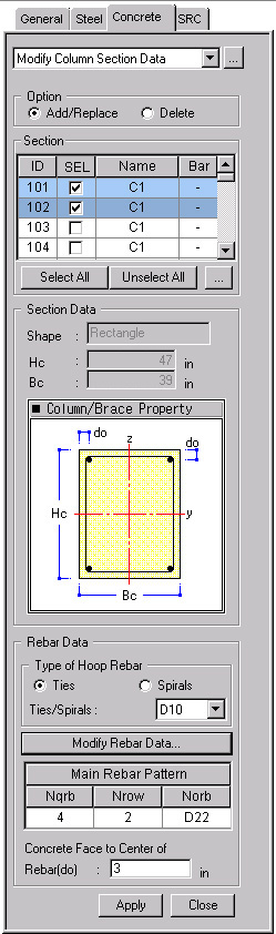
Enter the section dimensions and rebar data for RC column members for strength verification.
Call
From the Main Menu select Design > Concrete Design Parameter > Modify Column Section Data.
From the Menu tab of the Tree Menu select Design > Concrete Design Parameter > Modify Column Section Data.
Entry
First, select the members in the model and enter the following data :
OptionSelect Add/Replace or Delete.
Add/Replace: Add the newly entered values or update the previously entered values.
Delete : Delete the entered values. Data entry is not required when deleting.
|
|
Select the sections for which strengths will be checked. ID : Section Number SEL: Check on to select the members for which section changes are made and rechecked and the results are produced. Note Name : Section Name Bar: Status of rebar placement (In: rebars are placed, -: rebars are not placed)
Click
Display the section data for column members. Shape: Sectional shape of the members Hc: Height of the section (Diameter of a circular section) Bc: Width of the section
|
.jpg) : Display the following dialog
bar to enter/modify rebar data for the column section :
: Display the following dialog
bar to enter/modify rebar data for the column section :
.jpg)
Main Rebar Size (Norb): Main rebar standard size
Number of Main Rebars (Nqrb): Number of vertical rebars placed in the column section
Number of Rows (Nrow): Number of rows of vertical rebars placed in the column section
Tied/Spiral Rebar Space: Spacing of hoop rebars
Arrangement: Enter the number of shear rebars in each direction.
Y: Number of shear rebars in Y-dir. (to maximum of 9)
Z: Number of shear rebars in Z-dir. (to maximum of 9)
.jpg) : Enter the values or
the selection and close the dialog box.
: Enter the values or
the selection and close the dialog box.
.jpg) : Do not enter the values
or the selection and close the dialog box.
: Do not enter the values
or the selection and close the dialog box.
Concrete Face to Center of
Rebar(do)Distance between the center of the main rebars and the surface of the section. (cover thickness) (refer to Note 2)
.jpg) : Enter the values for
the selected members.
: Enter the values for
the selected members.
.jpg) : Close the entry dialog
box.
: Close the entry dialog
box.
Note
1
The dimensions entered for the analysis model determine the height (Hc)
and width (Bc) of the section. The sectional shape of the column members
defined in the analysis model must be circular or rectangular (refer to
"Section for Design").
Call
From the Main Menu select Design > Section for Design
Note
2
Enter the cover dimension of the main rebars for the column section. When
the cover is not specified (do = 0), strength verification will not proceed.
Note
3
The Definition of Column/Brace Rebar dialog box for a "Circular"-section
is as follows:
.jpg)
Note
4
Rebar data are required for strength verification for column members. If
any one of Main Rebar Size (Norb), Number of Main Rebars (Nqrb) and Number
of Rows (Nrow) is missing strength verification will not proceed.
The Number of Main Rebars (Nqrb) must be an even number. The value must be larger than 4 for rectangular sections and larger than 6 for circular sections.
Note
5
When the rebar data are repeatedly entered for the same section, the values
will be updated to the last values
entered.
Note
6
The entered rebar data can be reviewed in the Data Table arranged in the
order of section numbers. The user may Modify/Add and Delete items in the data table.
Access the data table following the procedure below.
From the Main Menu select Design > Concrete Design Parameter > Concrete Design Tables > Modify Column Section Data.
From the Tables tab of the Tree Menu select Design Tables > Concrete Design Table > Modify Column Section Data.
 : Select all section data
 : Unselect all section data
.jpg) : to modify the
sectional shape and dimensions. Display the Section for Design dialog
box (refer to "
: to modify the
sectional shape and dimensions. Display the Section for Design dialog
box (refer to "