Unbraced Length (L,Lb)
| ||
|
| ||
|
| ||
|
Enter the unbraced lengths for buckling about the strong (y-axis) and weak (z-axis) axes of the selected compression members.
Enter the laterally unbraced length for the compression flange of a member bent about its weak axis.
Note | ||
|
| ||
|
| ||
|
| ||
|
From the Main Menu select Design > General Design Parameter > Unbraced Length (L,Lb).
From the Menu tab of the Tree Menu select Design > General Design Parameter > Unbraced Length (L,Lb). | ||
|
| ||
|
| ||
|
First, select the members in the model, and then enter the following:
|
 Option
|
|
|
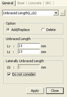
There are two entry methods.
<Method 1>
Enter the values directly in the Ly, Lz and Lb fields.
< Method 2>
Click the Ly, Lz or Lb field and select two nodes in the model. The straight distance between the two nodes is automatically calculated and entered.
 : Apply the entered
values to the selected members.
: Apply the entered
values to the selected members.
 : Close the entry Dialog
Bar.
: Close the entry Dialog
Bar.
Note
1
For members where the values of Ly and Lz have not been entered, the member
lengths calculated by the program based on the nodal coordinates of the
relevant beam (truss) elements are applied as the values of Ly and Lz.
Note
2
For members where the values of Lb have not been entered, Lz values are
set to Lb.
Note
3
If "All Beams/Girders are Laterally Braced" option is selected
in the Steel Design Code dialog box, this item is automatically selected
and Lb=0 is automatically set by default.
(Refer to "Steel
Design Code")
Note
4
If the values of Ly, Lz and Lb are repeatedly entered for the same member,
the values will be updated to the last values entered.
Note
5
The entered unbraced lengths and laterally unbraced lengths can be reviewed
in the data table arranged in the order of element numbers. The user may
Modify/Add and Delete items in the data table.
Access the data table following the procedure below.
from the Main Menu select Design > General Design Parameter > Unbraced Length (L,Lb)
From the Tables tab in the Tree Menu select Design Tables > General Design Table > Unbraced Length (L,Lb).