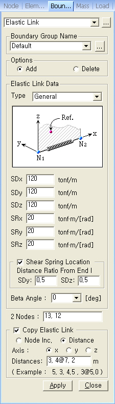
Create or remove elastic links. Two nodes are connected by an elastic
link and its stiffness is defined by the user.
From the Main
Menu select Model > Boundaries > Elastic Link.
Select Geometry
> Boundaries > Elastic Link in the Menu tab of the
Tree Menu.
Click to the right of Elastic
Link: Display the Elastic Link Table
Boundary Group Name
Select a Boundary Group
in which the specified boundary condition is included. Select "Default"
if Group assignment is unnecessary. Click to the right
to prompt the "Define
Boundary Group" dialog box to add, modify or delete Boundary
Groups.
Options
Add/Replace:
Enter or replace elastic links
Delete:
Delete previously entered elastic links
Elastic
Link Data
Type:
Assign an elastic link type.
General
Type: General elastic link (6dof)
Rigid
Type: Rigid link element
Revision of Gen 2010
Note
In
case of Rigid Type, the element stiffness is automatically calculated
based on the working model. The applied stiffness of the link can be checked
in the text output file (*.out) after performing analysis.
Tens.-only:
Tension-only elastic link
Comp.-only:
Compression-only elastic link
Note
When an elastic link is assigned as tension-only or compression-only, only
element's axial stiffness can be applied. The elastic link observes the Iteration method defined in Main
Control Data identical to tension- and compression-only.
Enter the tensile stiffness
and compressive stiffness of a spring symmetrically or asymmetrically.
Compression in a spring is defined to be the positive (+) displacement.
That is, the stiffness shown in the first quadrant of the left guide diagram
represents the stiffness of a spring subjected to compression.
Note Multi-linear elastic link
The slopes
in the external sections, which are not defined by the user, are based
on the same slopes defined by the last two nodes.
SDx:
Stiffness in the element's local x-direction
SDy:
Stiffness in the element's local y-direction
SDz:
Stiffness in the element's local z-direction
SRx:
Rotational stiffness about the element's local x-axis
SRy:
Rotational stiffness about the element's local y-axis
SRz:
Rotational stiffness about the element's local z-axis
Shear
Spring Location
Save
the locations of shear springs used in elastic link elements.
Distance
Ratio From End I
Specify the locations
of the shear springs relative to the length of the
elastic link elements starting from i-node.
Direction:
Enter the direction of a spring with respect to the node local coordinate
system
Beta
Angle: Angle defining the elastic link orientation
2 Nodes
Enter the node numbers for the 2 nodes to
be elastically linked.
Copy Elastic Link
Define simultaneously a number of elastic
links by copying the conditions assigned to an elastic link.
Node Inc.
Create a number of elastic link elements using a node increment.
Number
of Times: Number of copies
Node Increment:
Increment of node numbers
Distance
Create a number of elastic link elements using the distances between nodes.
Axis:
Assign an axis direction for copying the elastic link.
Distances:
Enter the number of repetitions and/or distances for copying the elastic
link.
 to the right of
  Boundary Group Name
 Revision of Gen 2010
 2 Nodes