Self Weight
| ||
|
| ||
|
| ||
|
Enter the self-weight of elements included in the model as applied loads, or modify or delete previously entered self-weight.
MIDAS/Gen uses the volume and density of each element to automatically calculate the self-weight included in the analysis model. The calculated self-weight can be applied in the GCS X, Y and Z-directions in the static analysis.
In addition, "Structure Type" determines if the mass effect due to the self-weight is to be considered in the dynamic analysis or in the calculation of the equivalent static seismic load.
The methods for considering the self-weight for different element types are as follows :
The self-weight of a truss, tension-only, compression-only or prismatic beam element is calculated by the cross sectional area and the density entered in "Section" and "Material", multiplied by the element length uniformly distributed over the entire length of the element.
For a beam element defined as a SRC section (Steel and Reinforced Concrete Composite Section), (refer to the "SRC" tab in Section) the weight is considered by separately calculating concrete and steel weights.
If a beam element is defined as Tapered Section (refer to the "Tapered" tab in "Section"), it is assumed that the self-weight varies linearly from one end to the opposite end.
When a panel zone offset distance is defined by "Panel Zone Effects", the self-weight of a beam element classified as a column member is accounted for by the full length between the two nodes. The self-weight of a beam element classified as a girder member (horizontal members connected to columns) is reflected by the full length between the two nodes less the panel zone offset distances at the two ends.
If an end offset distance is introduced in a prismatic beam element by "Beam End Offsets", it is assumed that the self-weight is uniformly distributed over the entire length between both nodes, irrespective of the offset.
In the case of a tapered section, it is assumed that the average self-weight is also uniformly distributed over the panel zone offset distances.
The self-weight of a plane stress, plate, plane strain or axisymmetric element is entered at the connection nodes as concentrated loads obtained by multiplying the element's cross sectional area, thickness and density, considering the area ratio.
The thickness data entered in "Thickness" (in-plane thickness in the case of plate elements) are used for plane stress, plate and wall elements. The unit width (1.0) and unit angle (1.0 radian) are used for plane strain and axisymmetric elements respectively.
The self-weight of a solid element is entered at each connection node as concentrated loads obtained by multiplying the volume by the density considering the volume ratio. | ||
|
| ||
|
| ||
|
| ||
|
From the Main Menu select Load > Self Weight.
Select Static Loads > Self Weight in the Menu tab of the Tree Menu. | ||
|
| ||
|
| ||
| ||
|
|
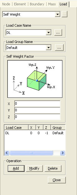
 Load
Case Name
Load
Case Name to the right to enter, additional load cases
and modify or delete existing load cases.
to the right to enter, additional load cases
and modify or delete existing load cases.
 :
: .
. .
.