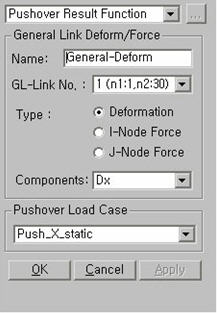
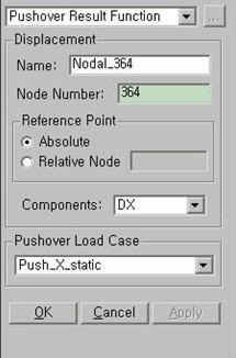
Pushover Result Function
| ||||||||
|
| ||||||||
|
| ||||||||
|
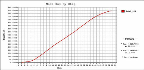
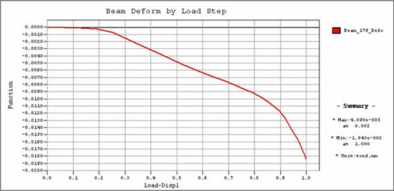
Specify the types of pushover analysis results, and define graphic output functions. Output functions can be also created or changed in Design > Pushover Analysis > Pushover Graph in the post-processing. | ||||||||
|
| ||||||||
|
| ||||||||
|
| ||||||||
|
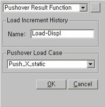
Click Define/Modify Function button in the Pushover Graph menu. | ||||||||
|
| ||||||||
|
| ||||||||
|
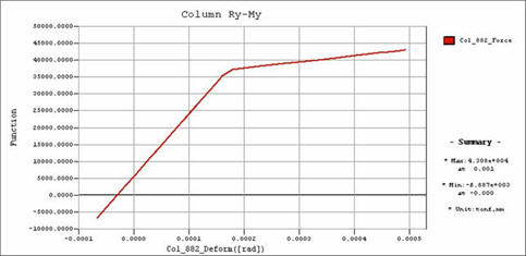
■ When Pushover Hinge Deform/Force is selected [Details…]
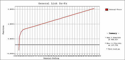
■ When General Link Deform/Force is selected [ Details…]
■ When Displacement is selected [Details…]
■ When Load Increment History is selected [Details…]
| ||||||||
|
|
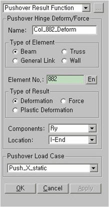
 Pushover Hinge Deform/Force