Concrete Design Results
| ||||||||||||||
|
| ||||||||||||||
|
| ||||||||||||||
|
Check the design results of RC members by numerical components and contours.
Reinforcing information such as rebar diameter, rebar spacing and required reinforcing steel area can be displayed.
Among the design results of RC members, the ratio of axial stress can be checked separately. (But this is applicable to the column and wall members only.)
Note1
Note 2 The design results for column and wall members can be checked by load combinations. On the other hand, the design results for beam members can be checked only for the most unfavorable load combination. Because in midas Gen, design results for beam members for each load combination are not stored. Display the number of tie legs for each direction. | ||||||||||||||
|
| ||||||||||||||
|
| ||||||||||||||
|
| ||||||||||||||
|
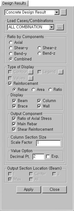
From the Main Menu select Design > Concrete Design Result. | ||||||||||||||
|
| ||||||||||||||
|
| ||||||||||||||
|
 to the right to enter,
add or modify load combinations (refer to
to the right to enter,
add or modify load combinations (refer to |
Contour |
Display the design results by contours. |
|
|
Ranges: Assign the contour ranges.
Note If the Contour Range values exceed the output values, they are entered at Rank 0 and Rank 11.
Number of
Colors: Assign the number of colors for the contour (select among
6, 12, 18 & 24 colors) Gradient
Fill: Display the color gradient (shading) in the contour. Draw Contour
Lines: Display the contour lines by colors. Colors: Assign or alter the colors of the contour.
Color Tables: Assign the type of Colors.
Contour Line: Assign the color for contour boundaries.
Element Edge: Assign the color of element edges to appear in the contour. |
 : Assign the coloring ranges
for contour lines. The user may assign specific colors for specific ranges.
: Assign the coloring ranges
for contour lines. The user may assign specific colors for specific ranges. : Control the color of each
range in the contour.
: Control the color of each
range in the contour.|
Legend |
Organize and display various references related to analysis results either to the right or left of the working window. |
|
|
Legend Position: Select the position of the legend in the output window Rank Value Type: Specify a type of values in the Legend and the number of decimal points. |
|
Values |
Display the selected design result components by means of numerical values. The font and color of the numbers can be
controlled in
Note When checking the Design Result on the screen, if the design result exceeds the limit value, the text is marked in red color. |
|
|
Decimal
Points: Specify decimal points of the displayed numbers Min &
Max: Display the minimum and maximum values Limit Scale(%): S et the screen limits for displaying design results relative to the maximum or minimum value
Note |

Reinforcement
Reinforcing results are produced. (Refer to Note.)
Rebar: Reinforcing bar diameter and spacing
Area: Required reinforcing steel area
Ratio: Steel reinforcement ratio
Display: Select the types of elements for which design reinforcing information will be displayed.
Output Component: Select the component to be displayed.
Ratio of Axial Stress
Main Rebar: Main rebar design result
Shear Reinforcement: Shear reinforcement design result
Column Section Size: Display of column section sizes can be scaled.
Value Option: Specify the number of decimal points for displayed values.
Note. Display of reinforcement
From the V600 of MIDAS/Gen, reinforcing information such as rebar diameter, rebar spacing and required reinforcing steel area can be checked in 'Concrete / SRC Design Result'.
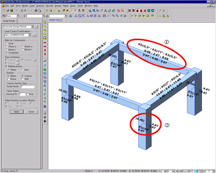
1) When 'Rebar' is selected in Reinforcement
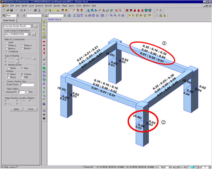
2) When 'Area' is selected in Reinforcement
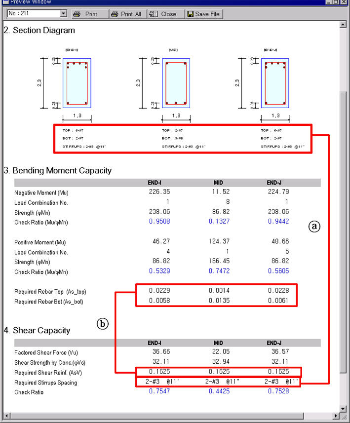
1. Rebar information for beams
Design results for the beam ① in the Figs. 1) & 2) above are produced.
3) Beam design results (Graphic)
The rebar diameter and spacing denoted by A in Fig. 3) are produced when 'Rebar' is selected in the Reinforcement option in Fig. 1). If 'Area' is selected, the required reinforcing steel areas are produced as denoted by B in Fig. 3).
2. Rebar information for columns
Design results for the column ② in the Figs. 1) & 2) above are produced.
4) Column design results (Graphic)
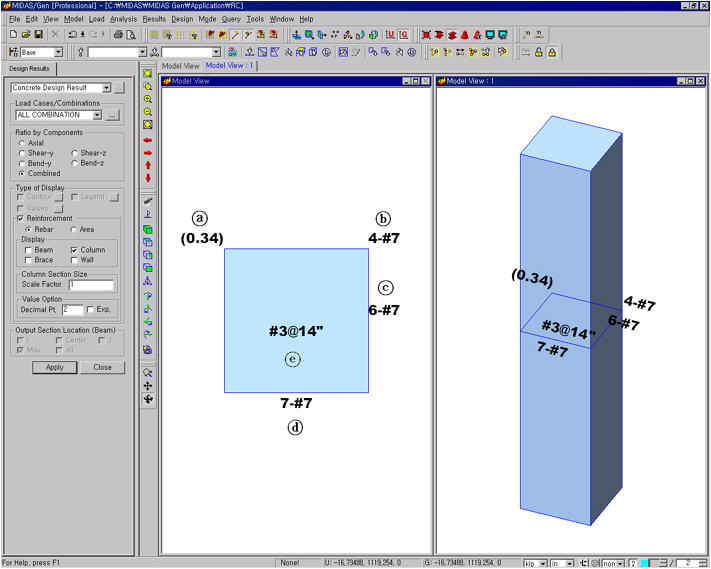
5) Reinforcing information of column by selecting 'Rebar'
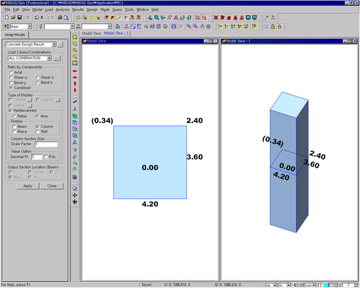
6) Reinforcing information of column by selecting 'Area'
The following outlines the reinforcing information in Figs. 5) & 6):
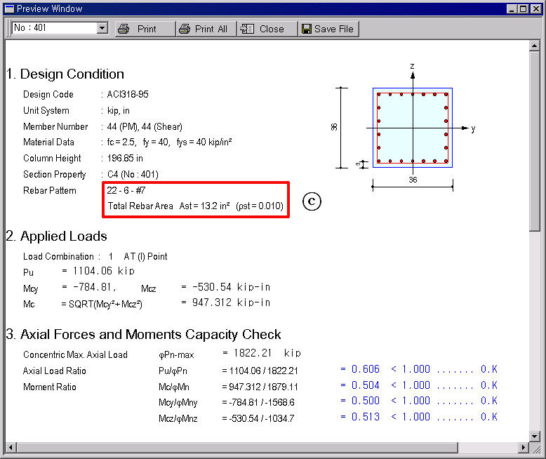
a. (Uc): Ratio of axial stress of the column (N/(fc' X Ag))
b. (As-corner): Number of corner rebars & rebar area
Ex.) 4-#7 = 4 X 0.6 = 2.4 in2
c & d (Asy, Asz): Number of rebars and rebar area on a single side
e. (Asv): Tie (shear) reinforcing spacing of column, Sc and rebar area within the spacing
Based on the reinforcing information noted at b, c & d above, the total number of rebars then becomes,
b+ ((c - 2) + (d - 2)) X 2 = 4 + ((6 - 2) + (7 - 2)) X 2 = 22
The number of rebars on one side (Asz)=5
22-6-#7 (See C in Fig. 4)
3. Rebar information for walls
Design results for the wall ① in the Figs. 7) & 8) are produced.
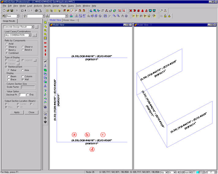
7) Reinforcing information of wall by selecting 'Rebar'
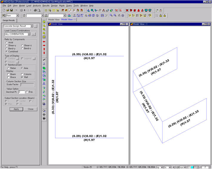
8) Reinforcing information of column by selecting 'Area'
The following outlines the reinforcing information in Figs. 7) & 8):
a. (Uc): Ratio of axial stress of the wall (N/(fc' X Ag))
b. (V)8-#4@16": Number of vertical rebars and spacing or vertical reinforcing steel area per unit length (in2/in)
c. (E)12-#3@6": Number of end rebars and spacing or total amount of reinforcing steel (in2)
d. (H)#3@11": Number of horizontal rebars and spacing or horizontal reinforcing steel area per unit length (in2/in)
 Output Section Location(Beam)
Check RC member design results by sectional locations. It can be used only when "Values" of "Type of Display" is selected.
I, Center, J: Represent the RC beam member's sectional locations. The user can not select the locations. It is automatically selected following the selection of "Max" or "All".
Max: Maximum values appear at every RC beam member.
All: Values appear at each location of RC beam members.
 : Apply the entered
values to the selected members.
: Apply the entered
values to the selected members.
 : Close the Entry Dialog
Bar.
: Close the Entry Dialog
Bar.