Steel Design Results
| ||||||||||||||
|
| ||||||||||||||
|
| ||||||||||||||
|
Check the design results of steel members by numerical components and contours. | ||||||||||||||
|
| ||||||||||||||
|
| ||||||||||||||
|
| ||||||||||||||
|
From the Main Menu select Design > Steel Design Result. | ||||||||||||||
|
| ||||||||||||||
|
| ||||||||||||||
|
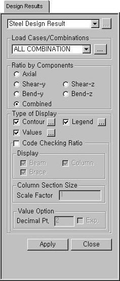
 Load Cases/Combinations
 to the right to enter,
add or modify load combinations (refer to
to the right to enter,
add or modify load combinations (refer to |
Contour |
Display the design results by contours. |
|
|
Ranges: Assign the contour ranges.
Note If the Contour Range values exceed the output values, they are entered at Rank 0 and Rank 11.
Number of
Colors: Assign the number of colors for the contour (select among
6, 12, 18 & 24 colors) Gradient
Fill: Display the color gradient (shading) in the contour. Draw Contour
Lines: Display the contour lines by colors. Colors: Assign or alter the colors of the contour.
Color Tables: Assign the type of Colors.
Reverse Contour: Check on to reverse the sequence of color variation in the contour.
Contour Line: Assign the color for contour boundaries.
Element Edge: Assign the color of element edges to appear in the contour. |
 : Assign the coloring ranges
for contour lines. The user may assign specific colors for specific ranges.
: Assign the coloring ranges
for contour lines. The user may assign specific colors for specific ranges. : Control the color of each
range in the contour.
: Control the color of each
range in the contour.|
Legend |
Organize and display various references related to analysis results either to the right or left of the working window. |
|
|
Legend Position: Select the position of the legend in the output window
Rank Value Type: Specify a type of values in the Legend and the number of decimal points. |
|
Values |
Display the selected design result components by means of numerical values. The font and color of the numbers can be
controlled in
Note When checking the Design Result on the screen, if the design result exceeds the limit value, the text is marked in red color. |
|
|
Decimal
Points: Specify decimal points of the displayed numbers Min &
Max: Display the minimum and maximum values Limit Scale(%): Set the screen limits for displaying design results relative to the maximum or minimum value
Note |

Code Checking Ratio
Strength check results for structural steel sections are displayed. (Refer to Note.)
Display: Select the types of elements for which design check ratios will be displayed.
Column Section Size: Display of column section sizes can be scaled.
Value Option: Specify the number of decimal points for displayed values.
Note
Strength check ratios for structural steel members are displayed as follows:
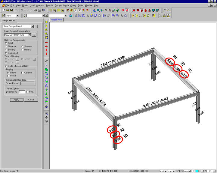
Strength check results for structural steel members
Strength check results (R1, R2 & R3) for columns and beams are shown above.
Beams
R1: Strength check stress ratio of steel members subject to axial force (compression or tension) and bending moments
R2: Combined stress ratio of steel members subject to normal stress and shear stress
R3: Stress ratio of steel members due to shear force only
Columns
R1: Strength check stress ratio of steel members subject to axial force (compression or tension) and bending moments
R2: Combined stress ratio of steel members subject to normal stress and shear stress
R3: To be upgraded in a future release (currently displayed as '0')
 :
Apply the displayed strength check ratios to the selected elements.
:
Apply the displayed strength check ratios to the selected elements.
 : Close the Dialog Bar.