Specify Allowable Stress
| ||
|
| ||
|
| ||
|
Use this function to enter the allowable stress coefficients. Often, the user may wish to define the allowable stresses rather than using the values calculated according to the applied design code during the strength verification of steel members. The coefficient values entered are ratios to the yield strength (Fy) of the relevant steel material. | ||
|
| ||
|
| ||
|
| ||
|
From the Main Menu select Design > Steel Design Parameter > Specify Allowable Stress.
From the Menu tab of the Tree Menu select Design > Steel Design Parameter > Specify Allowable Stress. | ||
|
| ||
|
| ||
|
First, select the members in the model and enter the following :
|
 Option
|
|
|
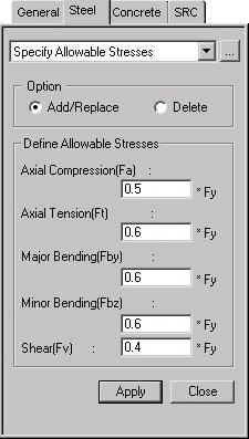
 : Apply the entered values
to the selected members.
: Apply the entered values
to the selected members.
 : Close the entry Dialog Bar.
Note
1
This can be applied only for the AISC-ASD89 and AIK-ASD83 design codes.
This is not applicable for the strength verification of steel-RC composite
column members.
Note
2
Fa stands for the allowable compressive stress for the compressive force
in the member's axial direction.
Note
3
Ft stands for the allowable tensile stress for the tensile force in the
member's axial direction.
Note
4
Fby and Fbz represent the allowable bending stresses for the bending moments
about the member's strong and weak axes respectively. Same values are
applied to all the bending stresses for the tension and compression fibers
irrespective of the signs of the bending moments.
Note
5
Fv stands for the allowable shear stress for the shear forces in the strong
and weak-directions. The same value applies to both strong and weak-directions.
Note
6
When the values of the allowable stress coefficients are repeatedly entered
for the same members, the values will be updated to the last values entered.
Note
7
The entered values for the allowable stress coefficients can be reviewed
in the data table arranged in the order of element numbers. The user may
Modify/Add and Delete items in the data table.
Access the data table following the procedure below.
From the Main Menu select Design > Steel Design Parameter > Steel Design Tables > Specify Allowable Stresses.
From the Tables tab of the Tree Menu select Design Tables > Steel Design Table > Specify Allowable Stresses.