Enter the standard sizes of main and sub-rebars used in the design of
beam, column and brace members. Also, enter the standard sizes and spacing
for vertical and horizontal rebars used in the design of shear wall members.
From the Main
Menu select Design
> Concrete Design Parameter > Design Criteria for Rebars.
From the Menu
tab of the
Tree Menu select
Design > Concrete Design Parameter > Design Criteria for Rebars.
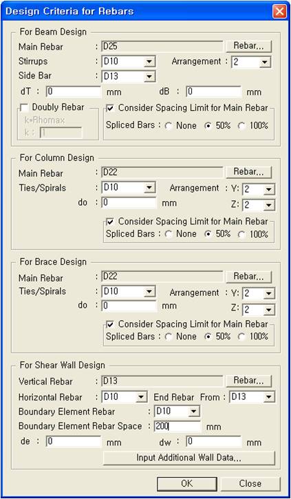
The following dialog box is used to enter
the data:
Design Criteria of Rebar dialog box
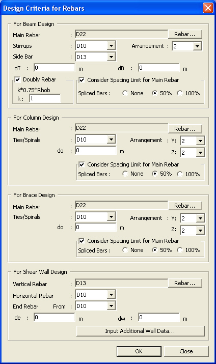
[Taiwan
Only]
Design
Criteria for Rebars dialog box (Taiwan)
For Beam Design (refer
to Note 1)
Enter the standard sizes of main and sub-rebars
and the placement locations of the main rebars used in the design of beam
members.
Main
Rebar: Main rebar standard sizes for the design of beam members
Click to display the Rebar
Size dialog box. Select with the mouse to enter the main rebar standard
sizes.
A maximum of 5 main rebar standard sizes
can be entered. ASTM and KS Standards may be used together.
Rebar
Size dialog box
: Apply the selection
and close the dialog box.
: Do not apply the selection
and close the dialog box.
Stirrup
Bar: Standard sizes for transverse reinforcing bars in beam design
Side Bar:
Standard sizes for side bars, used for bar placing. Beam strength is not
affected
Arrangement:
Number of shear reinforcement legs
Revision of Ver.7.5.0
Note
1. Under the IS456:2000 Concrete Design
Code, only an even number can be selected in the Arrangement field.
2. Limitations:
a. When an odd number is entered in the
Arrangement field and the specified concrete design code is changed to
IS456:2000, design is not performed for the corresponding members.
b. When an odd number is entered in the
Arrangement field and the user opens the Design Criteria for Rebar dialog
after changing the concrete design code to IS456:2000, a value of 2 is
automatically entered in the Arrangement field.
dT:
Distance between the center of the main rebars in the top layer of the
top bars and the top surface of the section (cover thickness)
dB:
Distance between the center of the main rebars in the lower layer of the
bottom bars and the bottom surface of the section (cover thickness)
Note
When calculating the maximum
number of rebars that can be placed within 1 layer, the side cover of
the beam shall be taken as the lesser of dT and dB specified in "Design
Criteria for Rebars".
Doubly Rebar
(Taiwan only): Option to use Doubly Reinforced Beam Design. In
the beam design, the program can consider both tension and compression
reinforcement. Compression reinforcement is considered in calculating
moment capacity when the applied design moment exceeds the maximum moment
capacity of a singly reinforced section. In other words, compression reinforcement
is considered when the required tensile rebars exceed the maximum tensile
rebar limit.
k*0.75*Rohb,
k
: Maximum tensile rebar limit can be specified by entering the
ratio (k) as a scale factor of the reinforcement limit (0.75ρb).
Note User Input of compressive
rebar ratio
1. Input the compressive rebar ratio for all beam members: Design >
Concrete Design Parameters > Design Criteria for Rebar
2. Input the compressive rebar ratio by beam members: Design > Concrete
Design Parameters > Design Criteria for Rebar by Members
Note
1. When this option is selected, Doubly Reinforced Beam Design is performed
irrespective of the application of Special Provisions for Seismic Design.
2. When “Special Provisions
for Seismic Design” and “Doubly Reinforced Beam Design”
are simultaneously applied, the larger of the compressive rebar ratio
as per “Special Provisions for Seismic Design” and the compressive
rebar ratio as per “Doubly Reinforced Beam Design” is applied.
Consider
Spacing Limit for Main Rebar : Check
on to apply the requirement of rebar spacing as per the design code. If
this option is checked off, the program does not consider rebar spacing
in performing automatic design.
Spliced
bar : Select a splicing option for the main rebars in the automatic
design. The default automatic design selects None.
=None:
Number of main rebars calculated without considering splicing
=50%:
Number of main rebars calculated considering 50%-splicing
=100%:
Number of main rebars calculated considering 50%-splicing
For Column Design (refer
to Note 2)
Enter the standard sizes of main and sub-rebars
for column members.
Main Rebar:
Main rebar standard sizes for the design of column members (The entry
is similar to that for "Main Rebar" of "For
Beam Design".)
Tie/Spiral
Bar: Standard sizes for tie bars used in column design
Arrangement:
Number of shear reinforcement legs
Note
For auto-design, the numbers of shear rebars in y & z axes can be differently
specified. Designed
rebars can be changed in Modify
Column Section Data.
do:
Cover distance from the center of main rebars
Consider
Spacing Limit for Main Rebar : Check
on to apply the requirement of rebar spacing as per the design code. If
this option is checked off, the program does not consider rebar spacing
in performing automatic design.
Note
The program did not provide required
rebar areas for the column design, which sometimes caused inconvenience
when the user tried to manipulate reinforcement. For this, checking off
“Consider Spacing Limit for Main Rebar” option allows the user
to find the required rebar area beyond the code required spacing.
Spliced
bar : Select a splicing option for the main rebars in the automatic
design. The default automatic design selects None.
=None:
Number of main rebars calculated without considering splicing
=50%:
Number of main rebars calculated considering 50%-splicing
=100%:
Number of main rebars calculated considering 50%-splicing
For Brace Design (refer to Note 3)
Enter the main and shear rebar sizes for
diagonal members.
Main Rebar:
Main rebar size for diagonal members (data entry is identical to that
for "Main Rebar" input method in "For
Beam Design".)
Tie/Spiral
Bar: Shear rebar size for diagonal members
Arrangement:
Number of shear reinforcement legs
Note
For auto-design, the numbers of shear rebars in y & z axes can be differently
specified. Designed
rebars can be changed in Modify
Column Section Data.
do:
Cover distance from the center of main rebars
Consider
Spacing Limit for Main Rebar : Check
on to apply the requirement of rebar spacing as per the design code. If
this option is checked off, the program does not consider rebar spacing
in performing automatic design.
Note
The program did not provide required rebar
areas for the column design, which sometimes caused inconvenience when
the user tried to manipulate reinforcement. For this, checking off “Consider
Spacing Limit for Main Rebar” option allows the user to find the
required rebar area beyond the code required spacing.
Spliced
bar : Select a splicing option for the main rebars in the automatic
design. The default automatic design selects None.
=None:
Number of main rebars calculated without considering splicing
=50%:
Number of main rebars calculated considering 50%-splicing
=100%:
Number of main rebars calculated considering 50%-splicing
For Shear Wall Design (refer to Note 4)
Enter the standard sizes of vertical and
horizontal rebars and the placement layout of vertical rebars for shear
wall members.
Vertical
Rebar: Standard sizes for vertical rebars used in shear wall design
Horizontal
Rebar: Standard size for horizontal rebars used in shear wall design
Boundary
Element Rebar: Standard sizes for Rebar used in Boundary Element
.
Boundary
Element Rebar Space:
Enter spacing of Rebar for Rebar entered in Boundary Element Rebar.
End Rebar
From: The minimum standard size to be used for end rebars for shear
wall design.
de:
Distance from the end of the shear wall member to the center of the first
row of the vertical rebars (or end rebars) (cover thickness)
dw:
Distance between the center of the end vertical rebars and the end of
the shear wall (cover thickness)
Click to display the dialog
box shown. Enter additional wall data such as rebar spacing and rebar
standard sizes used for the shear wall members, and select end rebar design
method, out-of-plane strength design, etc.
Input Additional Wall Data dialog box
Design of Out-of-plane Bending
Determine whether to design the wall for
a bending moment about the weak axis.
Spacing of Wall Rebars
Enter the spacings of the vertical and horizontal
rebars for every shear wall member.
Spacing
of Vertical Rebars: refer to Note
4
Click to display the Spacing
dialog box and, with the mouse, enter the spacings for the vertical rebars
in the shear wall member. Use "mm" or "in" for the
spacing unit.
Spacing
dialog box
List for Selection
Previously entered rebar spacings are listed.
List for Design
Select
and list the rebar spacings to be applied. A maximum of 50 spacings can
be selected.
: Delete selected spacings
from the list.
User Input Spacing
Click to add a new spacing
to the List for Selection after entering a new spacing.
: Enter the selection
and close the dialog box.
: Do not enter the selection
and close the dialog box.
Spacing of Horizontal Rebars:
refer to Note
4
End Rebar Design Method
Select the method of designing shear walls
considering end rebars.
Not Used
Method-1:
Place the rebars at equal intervals over the entire wall length (no end
rebars)
Auto Calculation
Method-2:
Assuming that the wall is reinforced uniformly at an equal spacing over
the entire length of the wall, determine additionally required rebars,
then place the rebars at the ends and the center part.
Method-3:
Assuming that the vertical rebars at both ends of the wall resist all
the axial force (Pu) and the bending moment (Mu), determine the required
reinforcing steel for the shear force resisted by the remaining part.
Method-4:
Identical to Method-2 and end rebars placed from 2EA
Spacing of End Rebars
Enter the spacing of end rebars used in the
shear wall design.
Dist1:
Spacing of end rebars in the case of 4 end rebars
Dist2:
Spacing of end rebars in the case of 6 end rebars
Dist3:
Spacing of end rebars in the case of 8 end rebars
: Enter the selection
and close the dialog box.
: Cancel the current
operation.
Note
1
When the standard rebar sizes for the main or sub-rebars for beam members
have not been entered, the following standard sizes are used:
Main
Rebars: #9
Stirrup Bars: #4
Side Bars: #5
If dT and dB are not entered
(ie. 0), the program uses the larger of 2.5"(63.5mm) and H/10, but
not exceeding 3 inches.
Note
2
When the standard rebar sizes for the main or sub-rebars for column members
have not been entered, the following standard sizes are used :
Main
Rebars: #9
Tie Bars: #4
If d0
is not entered (ie. 0), the program uses the larger of 2.5"(63.5mm)
and H/10, but not exceeding 3 inches.
Note
3
When the standard rebar sizes for the main or sub-rebars for brace members
have not been entered, similarly apply the standard sizes used for column
members.
Note
4
When the standard rebar sizes and the spacings of rebars for the design
of shear wall members have not been entered, the following standard sizes
and spacings are
used:
Vertical
Rebars : #5
Horizontal Rebars : #4
End Rebars : #4
Spacing of Vertical Rebars
: @4'', @6'', @8'', @12'', @16''
Spacing for Horizontal Rebars :
2''
The standard rebar sizes
or rebar spacings for design can be selectively limited to satisfy the
design purpose. If the values dw and de are not entered (in case where
they are 0), 2 inches (5.08cm) are automatically used.
 For Beam Design
  to display the Rebar
Size dialog box. Select with the mouse to enter the main rebar standard
sizes.
to display the Rebar
Size dialog box. Select with the mouse to enter the main rebar standard
sizes.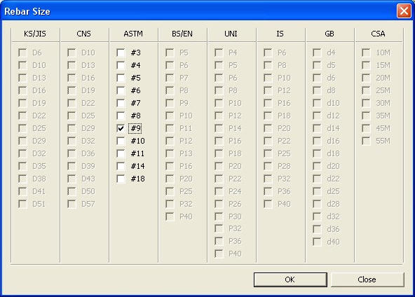
 : Apply the selection
and close the dialog box.
: Apply the selection
and close the dialog box. : Do not apply the selection
and close the dialog box.
: Do not apply the selection
and close the dialog box. Revision of Ver.7.5.0
 to display the dialog
box shown. Enter additional wall data such as rebar spacing and rebar
standard sizes used for the shear wall members, and select end rebar design
method, out-of-plane strength design, etc.
to display the dialog
box shown. Enter additional wall data such as rebar spacing and rebar
standard sizes used for the shear wall members, and select end rebar design
method, out-of-plane strength design, etc.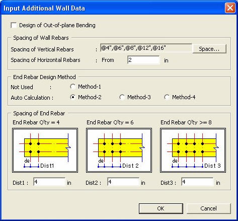
 to display the Spacing
dialog box and, with the mouse, enter the spacings for the vertical rebars
in the shear wall member. Use "mm" or "in" for the
spacing unit.
to display the Spacing
dialog box and, with the mouse, enter the spacings for the vertical rebars
in the shear wall member. Use "mm" or "in" for the
spacing unit.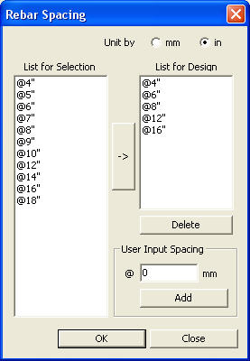
 : Delete selected spacings
from the list.
: Delete selected spacings
from the list. to add a new spacing
to the List for Selection after entering a new spacing.
to add a new spacing
to the List for Selection after entering a new spacing.  : Cancel the current
operation.
: Cancel the current
operation.