Floor Diaphragm Masses
When the model is a building, enter the floor mass data for stories.
There are two methods for entering floor masses.
1. Calculate and enter the floor mass, rotational mass moment of inertia and coordinates of the center of mass
2. When the floor plane is consisted of line masses (straight line, arc) or surface masses (rectangle, triangle, circle), the geometric shapes of the relevant mass units and the positions are specified. The program then automatically computes the floor mass, the rotational mass moment of inertia and the center of mass
The function can be repeatedly used for a given floor plane when the floor plane is consisted of several units of different shapes.
The entered mass data are used to automatically calculate equivalent static seismic loads according to the seismic design codes and used for dynamic analysis.
Floor Diaphragm Masses is used in connection with Model > Building > Story, Control Data.
In order to use the function, the Z-axis of the building model must orient opposite to the gravity direction, and "Consider Floor Diaphragm" in Story must be assigned to the relevant floors to activate Rigid Diaphragm Action for each story.
The calculated or entered mass data are automatically entered at the Diaphragm Centers, that is, the center of mass is auto-calculated for each story. Only the components in the GCS x and y directions and the rotational mass moment of inertia about the z-axis are considered.
From the Main Menu select Load > Static Load > Structure Loads/Masses > Nodal Masses > Floor Diaphragm Masses.
|
 Diaphragm Mass
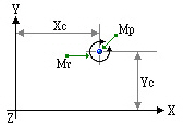
Point Mass
|
|
Mp : Point mass in GCS X, Y-directions (Translational Mass)
Mr : Rotational Mass Moment of Inertia about GCS Z-direction at the point mass position
Xc, Yc : GCS coordinates of the center of the point mass |
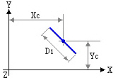
Line Mass
|
|
Ml : Mass per unit length (Mass/Length)
D1 : Length of line mass
Xc, Yc : GCS coordinates of the center of the line mass |
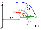
Circular Arc Mass
|
|
Ml : Mass per unit length (Mass/Length)
Xc, Yc : GCS coordinates of the center of the circular arc volume
D1 : Angle of the circular arc (Degree)
D2 : Radius of the circular arc
D3 : Angle of inclination from the center of the circle to the center of gravity of the circular arc relative to GCS X-axis (Degree) |
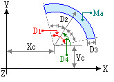
Circular Area Mass
|
|
Ma : Mass per unit area (Mass/Area)
Xc, Yc : GCS coordinates of the center of the circle
D1 : Internal angle of the arc strip area (Degree)
D2 : Radius of the arc strip area
D3 : Radial strip width
D4 : Angle of inclination from the center of the circle to the center of gravity of the arc strip area relative to GCS X-axis (Degree) |
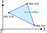
Triangular Area Mass
|
|
Ma : Mass per unit area (Mass/Area)
X1, Y1 : Coordinates of a corner of the triangular area
X2, Y2 : Coordinates of the 2nd corner of the triangular area
X3, Y3 : Coordinates of the 3rd corner of the triangular area |
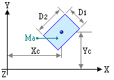
Rectangular Area Mass
|
|
Ma : Mass per unit area (Mass/Area)
Xc, Yc : GCS coordinates of the center of the rectangular area
D1 : Length of one edge of the rectangular area
D2 : Length of the other edge of the rectangular area perpendicular to D1 |
Note
When Floor Diaphragm is considered, mass center can be checked from Query>Story Mass Table.