|
 Load Case Name Load Case Name
Assign the load case name. Click  to the right to enter additional load cases, and modify or delete existing load cases. to the right to enter additional load cases, and modify or delete existing load cases.
Load Group Name
Select the desire Load Group that will include the entered Specified Displacements of Supports data. Select "Defualt", if a Group assignment is unnecessary. Click to the right to add, modify or delete Load Groups.
Options
Add: To enter new or additional specified displacements at selected nodes assigned with constraints
Replace: To replace previously entered specified displacements at selected nodes assigned with constraints
Delete: To delete previously entered specified displacements at selected nodes assigned with constraints
Displacements (Local Direction)
Enter specified displacements with respect to the GCS or nodal local coordinate system.
If the nodal local coordinate system has already been defined for specific nodes the data for the nodes are entered with respect to the NCS.
Dx: GCS or nodal local x-direction component of the specified displacement
Dy: GCS or nodal local y-direction component of the specified displacement
Dz: GCS or nodal local z-direction component of the specified displacement
Rx: Specified rotation component about GCS or NCS X-axis
Ry: Specified rotation component about GCS or NCS Y-axis
Rz: Specified rotation component about GCS or NCS Z-axis
Note 1
The specified displacements are considered as load cases in midas Gen. Thus, the specified displacements can be combined with other load cases. Note the following when generating load combinations in a model applied with specified displacements.
If specified displacements are assigned to a node, the relevant degrees-of-freedom of the node are automatically constrained.
The nodes assigned with specified displacements behave like Support even for other
load cases that do not contain specified displacements.
In other words, the function serves to define "Specified Displacements of Supports" in midas.
Note 2
When the specified displacements are entered at the specific construction stage, the load case for the specified displacement is assigned to CS : Dead load or CS : Erection.
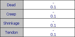
But the specified displacement is applied based not on the CS : Dead load or CS : Erection, but on the CS : Summation. For example, if the nodal displacements in the preceding stage are shown in the table below and the user enter +0.1 as the specified displacement, the specified displacement of 0.5 will be applied in order to obtain the final displacement (Dead + Creep + Shrinkage + Tendon) of 0.1.
|