Response Spectrum Load Cases
Enter the load cases, spectrum functions and loading directions for response spectrum analysis.
The procedure for response spectrum analysis in midas Gen is outlined below.
1. Enter mass data using various ways provided in the Main Menu, Model>Masses.
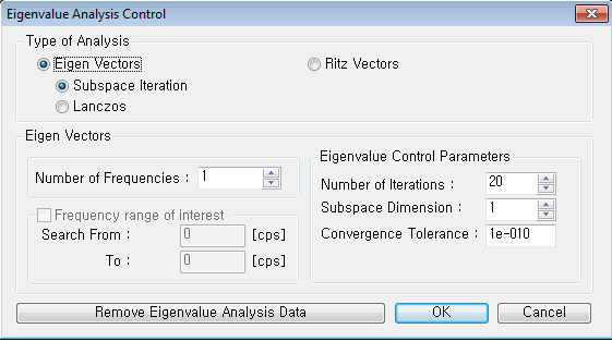
2. Enter the number of modes and necessary data for eigenvalue analysis in Eigenvalue Analysis Control.
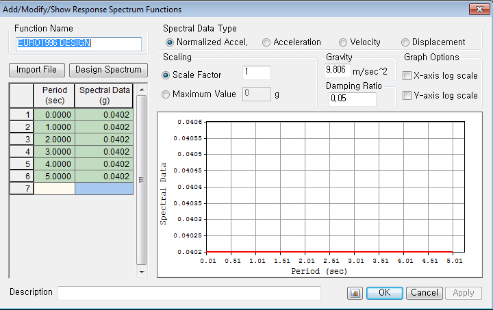
3. Define spectrum data to be applied in Response Spectrum Functions.
4. Set options related to response spectrum analysis in Response Spectrum Load Cases.
5. Perform analysis by clicking  Perform Analysis or using the Main Menu, Analysis>Perform Analysis.
6. When an analysis is completed, analyze the results using load cases or load combinations with various post-processing functions from the Results menu.
From the Main Menu select Load > Seismic > Response Spectrum Data > Response Spectrum Load Cases.
|
Enter the name of the response spectrum analysis case. The name is used for load combinations. (Refer to "Combinations")
X-Y: Apply the response spectrum loads in the horizontal directions (directions parallel to GCS X-Y plane) of the structure.
Z: Apply the response spectrum loads in the vertical direction (GCS Z-direction) of the structure.
Select this option to automatically take the excitation angle of response spectrum as the major-axis direction of a building.
Major : Major-axis direction
Ortho : Major-axis direction + 90˚
Note "Major" and "Ortho" must be defined in the identical Response Spectrum function. For example, if we define"RX" load case as "Major", "RY" load case must be defined as "Ortho". After performing the Response Spectrum Analysis, excitation angle of the structure will be automatically entered in the "Excitation Angle" field.
When the seismic excitation direction is parallel to the X-Y plane (Direction='X-Y'), the sign of the seismic loading angle [Degree] is referenced to the Z-axis using the right hand rule. The angle is zero at the GCS X-axis.
Scale factor for the entered response spectrum excitation
A multiplier factor for periods calculated by eigenvalue analysis.
Non-structural members are typically excluded in the analytical model, but rather treated as loads. Such omission can result in higher periods than actually are. This factor applies to all the natural periods calculated by eigenvalue analysis for response spectrum analysis. This functionality becomes useful when we wish to account for stiffness contribution of non-structural elements in which case we may wish to reduce the calculated periods.
Note
|
 Modal Combination Control
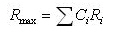
Enter the method of mode combination and specify whether to restore the signs of response spectrum analysis results. midas Gen allows the user to select the modes for a modal combination so that the major modes of a structure can be combined. [Details...]

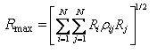
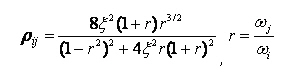
 : the representative maximum value for a particular response
  : the peak value of the particular response for the i-th mode
 : the ratio of the natural frequency of the i-th mode to that of the j-th mode
 : damping ratio
Spectrum Functions
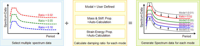
Select pre-defined design spectrum functions, which will be used to define a number of response spectrum load cases. A same spectrum from a code may result in a number of spectrum functions depending on the damping ratio. Therefore, this becomes useful when the user wishes to define a number of spectrum functions based on different damping values in a structure.
Function Name
Select a spectrum function name. If spectral functions have not been defined, click the  button located at the bottom of the dialog box to define spectrums. (Refer to "Response Spectrum Functions")

Apply Damping Method
Damping Method : Define the damping property of a structure using multiple design spectrums.
 : to modify the existing damping ratio
 : to remove the existing damping ratio
 Mass and Stiffness Proportional

Correction by Damping Ratio : When a single spectrum is selected, a modifying equation is used to adjust the spectrum to apply to each mode having

Note 1
The modifying equation can not be used when multiple spectrums are selected because the spectrums are interpolated based on the damping ratios. A damping ratio can not go beyond the upper and lower bound damping ratios of the spectrum.
Note 2
When combining modal responses, using Complete Quadratic Combination (CQC) will reflect damping for each mode without the use of the modifying equation. The combining method can be specified in Modal Combination Control.
Interpolation of Spectral Data
Select the method of interpolating the response spectrum load data.
Linear : Linear interpolation method
Logarithm : Log-scale interpolation method
Accidental Eccentricity
Select whether to include accidental eccentricity moments in the calculation of response spectrum loads. Click  to prompt the Accidental Eccentricity for Response Spectrum Load dialog box.
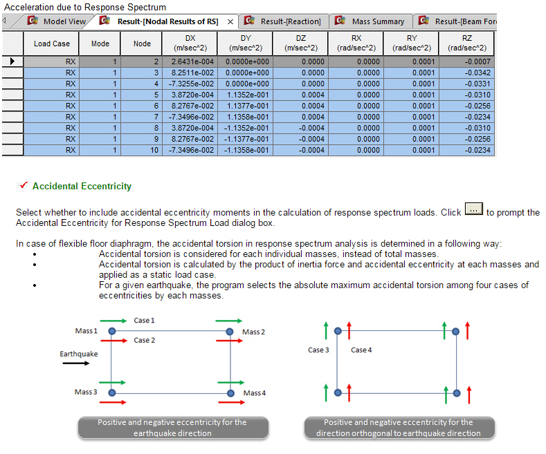
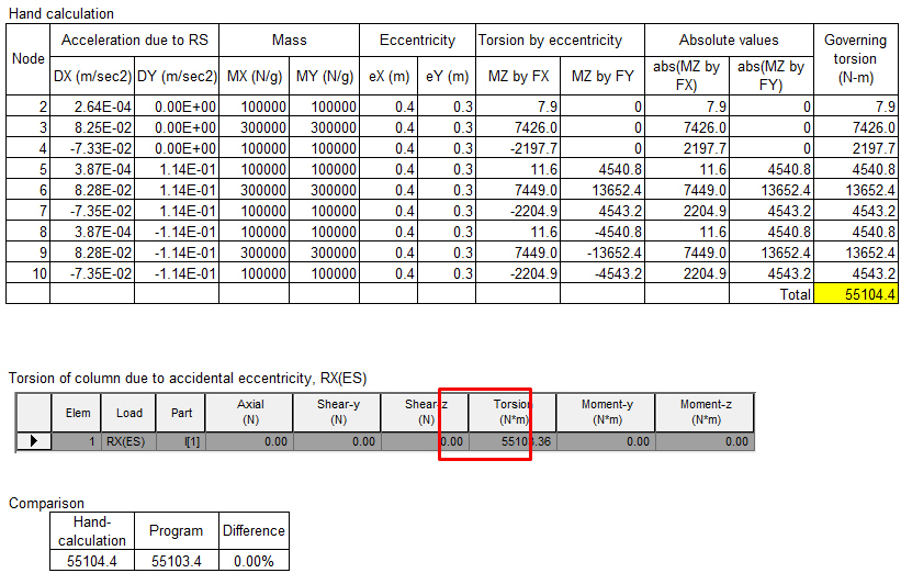
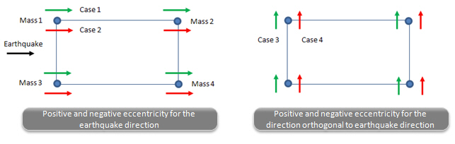
In case of flexible floor diaphragm, the accidental torsion in response spectrum analysis is determined in a following way:
-
-
-
Accidental torsion is considered for each individual masses, instead of total masses.
-
Accidental torsion is calculated by the product of inertia force and accidental eccentricity at each masses and applied as a static load case.
-
For a given earthquake, the program selects the absolute maximum accidental torsion among four cases of eccentricities by each masses.
-
-
Note 1
Using this functionality, we can check the analysis results from the auto-generated load case (Es: Dynamic load case name), which reflects the accidental eccentric moments.
Note 2
The magnitudes of the applied accidental torsional moments can be checked in Results > Result Tables > Story Shear (Response Spectrum Analysis)
Note 3
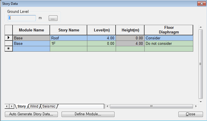
This function becomes activated only when Model > Building > Story Data is defined.
Eccentricity Data
Automatic
An eccentricity in terms of a percentage of plan dimensions is automatically considered.
User Defined
The user defines the eccentricities individually.
Consider Eccentricity below G.L
Check on: Eccentricity is considered for both above-ground and underground floors.
Check off: Eccentricity is considered only for above-ground floors.
Limit Minimum Accidental Torsional Moment
Calculate accidental torsion equal to story shear force multiplied by accidental eccentricity.
Description
Enter a brief description.
Operations
 Enter new or additional response spectrum analysis load cases
Enter the above entries and click  .
.
Modify previously entered response spectrum analysis load cases
Select a response spectrum analysis load case from the list in the dialog box and click  .
.
Delete previously entered response spectrum analysis load cases
Select a response spectrum analysis load case from the list in the dialog box and click  .
.
In addition to the spectrum functions and the loading conditions of the response spectrum, access the following functions to enter additional data required for a response spectrum analysis:
 : Eigenvalue Analysis Control... is invoked to check dynamic properties of a structure
 : Response Spectrum Functions... is invoked to define spectrums.
 Revision of Gen 2015 (v1.1)
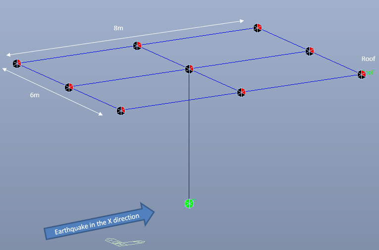
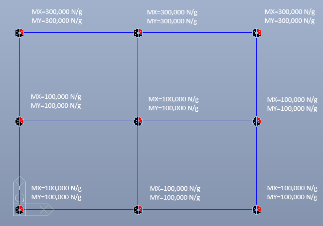
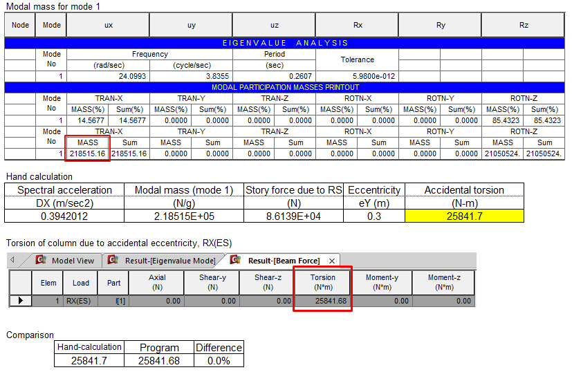
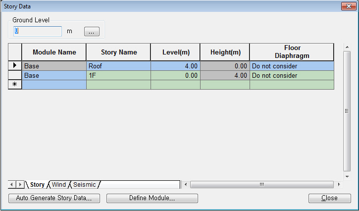
Q1. How midas Gen calculates Accidental Eccentricity when Floor Diaphram is not considered?