To create a Link element
for an Analysis model. Links are of two types- Rigid and Elastic Links.
Applicable Modules:
Tunnel
Slope
Soft
Ground
Foundation
Seepage
Dynamic
From the Main Menu,
select Model
> Element > Link Element
From the Command
Line, type 'LinkElement' or 'CEL'
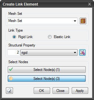
Mesh Set
Enter the name of the mesh set. Click to
Add, Modify or Delete mesh sets.
Link
Type
Rigid Link
Rigid Link restrains
the geometric relative displacement of a structure. Rigid Link restrains
geometric relative displacement in one or more degrees of freedom at a
node. The node that controls the restraints is Master Node, and node(s)
that is dependent or restrained is Slave Node.
Elastic Link
An
Elastic Link, which is assigned user defined stiffness, connects two nodes.
An Elastic Link behaves like an element.
Note:The
user may use a Truss or Beam element to connect two nodes but determining
the size and the directional stiffness may not be appropriate. In such
a case, the use of Elastic Link which can connect two nodes with given
stiffness is recommended.
Structural
Property
Enter the Structural
Properties of the Link element. Click to Add, Modify or
Delete Structural Properties.
Select
Node(s)
Link
Type: Rigid Link
Select
Master Node
Select a node which
will control the displacements of subordinate (slave) nodes.
Select
Slave Node(s)
Select node(s) which
will be restrained by the master node.
Link
Type: Elastic Link
Select
Node 1
Select the first node
to be elastically linked.
Select
Node 2
Select the second Node
to be elastically linked. Elastic link is created between two nodes only.
The dialog box will
be initialized.
After creating the pile elements, the dialog
box will close upon clicking.
Click
or press the ESC key to close the dialog box.
After creating the link, the work process
will switch to the state of Select Master Node (Select Node 1) upon clicking.


 Add, Modify or Delete mesh sets.
 to Add, Modify or
Delete Structural Properties.
to Add, Modify or
Delete Structural Properties. The dialog box will
be initialized.
The dialog box will
be initialized.  After creating the pile elements, the dialog
box will close upon clicking.
After creating the pile elements, the dialog
box will close upon clicking. or press the ESC key to close the dialog box.
  After creating the link, the work process
will switch to the state of Select Master Node (Select Node 1) upon clicking.
After creating the link, the work process
will switch to the state of Select Master Node (Select Node 1) upon clicking.