To create a Surface Spring
element for an Analysis Model.
Elastic
boundary (spring) element is mainly used to consider the stiffness of
adjacent structures or ground at the boundaries of a model. Surface Spring
is especially designed to readily model surface boundary conditions for
curved or planar structures in contact with ground.
Surface
elements are selected and the modulus of subgrade reaction for unit area
is entered. The stiffness of the spring at each node pertaining to the
effective (tributary) area is calculated by the product of the effective
area and the modulus of subgrade reaction. If the support such as the
ground needs to resist only compression, select Elastic Link (Compression-only)
and enter the modulus of subgrade reaction.
Applicable Modules:
Tunnel
Slope
Soft
Ground
Foundation
Seepage
Dynamic
From the Main Menu,
select Model
> Element > Surface Spring
From the Command
Line, type 'SurfaceSpring' or 'CESS'
Mesh Set
Enter
the name of the mesh set. Click to Add, Modify or Delete
mesh sets.
Object
Type
Select the object for
which surface spring will be created.
Frame
Element Boundary
Element Width
Support stiffness is
calculated from the effective (tributary) area (width x tributary length).
After creating the pile elements, the dialog
box will close upon clicking.
Click
or press the ESC key to close the dialog box. .
After creating the
surface spring, the work process will switch to the state of Select 1D
Element upon clicking.
Note:
Spring
is created from the effective area of a node multiplied by the modulus
of subgrade reaction. The diagram below illustrates the creation of surface
spring at the boundaries of 2 square elements with each side being 5m
long. The effective areas are 2.5m^2 each for the
first and last nodes and 5m^2 for the center node. With
the modulus of subgrade reaction, 100tonf/m^3, the converted spring stiffness
is calculated by multiplying the effective areas by the modulus of subgrade
reaction, resulting in 250tonf/m for the end nodes and 500tonf/m for the
center node.
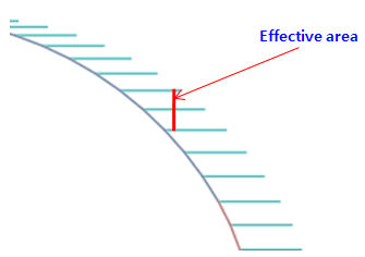
Elastic Link &endash; Creating elastic links from
selecting Frame/Element Boundary is identical to the Spring conversion
method. Elastic link is often used for lining structural analysis as a
boundary condition and as such Elastic Link is often created on curved
elements. As shown below, the effective areas for nodes on the curved
elements are calculated on the basis of ΔZ (difference in height between
two nodes) rather than the actual length, ΔL, when creating Elastic Links
on the curve in the X-direction.
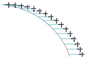
When
surface spring is created as elastic link, Compression-only or Tension-only
may be selected.
Elastic
Link can be created in the Global +X, -X, +Z, -Z and Normal(+,-) directions.


 Add, Modify or Delete
mesh sets.
Add, Modify or Delete
mesh sets. The dialog box will be initialized.
  After creating the pile elements, the dialog
box will close upon clicking.
After creating the pile elements, the dialog
box will close upon clicking. or press the ESC key to close the dialog box.
  After creating the
surface spring, the work process will switch to the state of Select 1D
Element upon clicking.
After creating the
surface spring, the work process will switch to the state of Select 1D
Element upon clicking.