Auto-generate Boundary Element
Auto-generate the boundaries of a ground model for dynamic analysis.
Applicable Modules:
Ground |
Slope |
Soft Ground |
Foundation |
Seepage |
Dynamic |
From
the Main
Menu, select Model
> Element > Auto-generate Boundary Element
![]()
From the Command Line, type 'BoundaryElement' or 'BE'
Mesh Set Name
Select the mesh sets around which boundary elements will be automatically generated. Boundary elements are auto-generated at the far-left, the far-right and the base of the selected mesh sets. Based on the material properties, different spring constants are generated.
Boundary Element
Elastic Boundary
Select in case the boundary is considered elastic.
Modulus of Elasticity Estimate Factor α
A factor adjusting the modulus of elasticity. The default value is 1.
Damping Boundary
Select in case the boundary is considered viscous.
Fixed Base
Select in case a fixed boundary condition needs to be imposed to the base of the ground model.
![]() After creating the boundary condition automatically, the dialog
box will close upon clicking.
After creating the boundary condition automatically, the dialog
box will close upon clicking.
![]() Click the ESC key to close the dialog box.
Click the ESC key to close the dialog box.
Note: Method of generating Elastic Boundary element
Use Elastic Springs for the boundary condition of the ground model for Eigenvalue and Response Spectrum Analysis. The following method is recommended for generating elastic springs:
1) Calculate Kv0 from the modulus of elasticity entered in Ground Material Property using the equation below.
![]()
Deformation Modulus (Eo) obtained from the Tests below (kgf/cm^2) |
α |
|
Normal Condition |
Earthquake Condition |
|
½ of deformation modulus obtained from the cyclic curve of 30cm diameter Plate Loading Test |
1 |
2 |
Deformation modulus measured in boring hole |
4 |
8 |
Deformation modulus obtained from Uni-axial or Tri-axial Test on a specimen |
4 |
8 |
Deformation modulus estimated by Eo=28N using the N-value of Standard Penetration Test |
1 |
2 |
where, Eo is Modulus of elasticity of ground, α is a Factor based on the test types (right column in the table above)
2) From the calculated Kv0, modulus of subgrade reaction, Kv (=Kh) is calculated.
where,
![]() ; Av is the area of the
ground spring to be created.
; Av is the area of the
ground spring to be created.
The model below illustrates the area of Ground A, Av=1m (left length of the model)*1m (unit width for 2D analysis)=1m^2 and the width Bv, 1m=100cm.
Likewise, the effective width of Ground B is Bv=√(20000)cm=141.42136cm.
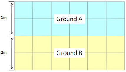
Finally, the modulus of subgrade reaction, K, is calculated, and the point springs are created at the nodes, reflecting the elements’ areas.
Ground |
E (tonf/m^2) |
Kyo |
A (cm^2) |
B |
K (tonf/m^3) |
α |
Ground A |
1000 |
3.3333 |
1.00E+04 |
100 |
1351.186643 |
1 |
Ground B |
2000 |
6.6667 |
2.00E+04 |
141.4213 |
2083.845925 |
1 |
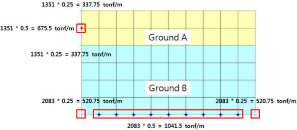
The spring constant for the base (Z direction) is the same as that in the X-direction. (Element length*width (1m)). Since it is a cross-section, only the effective length of the element is considered.
Where the two different ground layers are in contact, 2 overlapped boundary elements are created.
Note: Method of generating Damping Boundary element
The boundary condition of Damping Boundary elements is required in order to perform Time History Analysis of the model. The Damping Boundary is generated as follows:
1) Cp & Cs Calculations
- Cp & Cs are calculated using the equations below.
where,
λ-Volumetric modulus of elasticity; G-Shear modulus; E-Modulus of elasticity; v-Poisson’s ratio and A- cross-sectional Area.
Only Cp and Cs are calculated as the area is automatically considered in Surface Spring generation.
Ground |
Modulus of Elasticity, E (tonf/m^2) |
Volumetric Modulus of Elasticity, λ (tonf/m^2) |
Shear Modulus, G (tonf/m^2) |
Unit Weight, W (tonf/m^3) |
Poisson's Ratio, Y |
P-wave, Cp (tonf.sec/m^3) |
S-wave, Cs (tonf.sec/m^3) |
Ground A |
1000 |
864.19753 |
370.37037 |
1.8 |
0.35 |
17.1605 |
8.2437 |
Ground B |
2000 |
1459.531181 |
751.87969 |
2 |
0.33 |
24.5792 |
12.381 |
The unit of Cp and Cs, tonf.sec/m^3 is multiplied by the Area resulting in the unit tonf.sec/m for the spring for the Damping Boundary element.
The parameters for Ground Material Properties are entered in the process of modeling by the user. The Volumetric Modulus of Elasticity and the Shear Modulus are calculated from the Modulus of Elasticity and the Poisson’s Ratio. Accordingly, no further data is required to create Damping Boundary elements.
In case Damping Boundary elements are required to be automatically generated, the Springs are automatically calculated using the elements’ areas (effective length*unit width) as shown below:
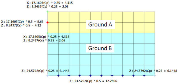
The Cp is entered in the parameter in the direction perpendicular to the nodes at which the springs are generated, and the Cs is entered in the parallel direction.
For example, the spring constant Cx generated at the left and right sides of the model is Cp for each ground layer, and Cz becomes Cs. In the case of the base of the model, the spring constant Cz becomes Cp.