Live Load Reduction Factor
Use this function to reduce the live loads for columns, shear walls or foundations when calculating the required axial strength.
Enter the basic data required to calculate the live load reduction factors.
Note
This function should be used when applying the live loads specified in the KS "Regulations related to structural criteria in the building codes", 1996. For other design standards, refer to Modify Live Load Reduction Factor where reduction factors can be specified for individual members.
From the Main Menu select Design > General Design Parameter > Live Load Reduction Factor.
From the Menu tab of the Tree Menu select Design > General Design Parameter > Live Load Reduction Factor.
The following dialog box is used to enter the reduction factors:
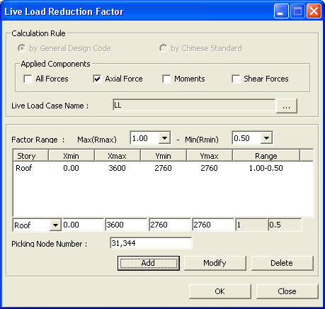
Live Load Reaction Factor dialog box
 Applied Components
Select the types of forces to which Live Load Reduction factors are applied.
All Forces
Axail Force
Moments
Shear Forces
Note
This functionality is not applicable for beam members. Live load Reduction Factors can be assigned in Design > General Design Parameter > Modify Live Load Reduction Factor.
Live Load Case Name
Name of the live load
Click ![]() to display the live load cases entered during the generation of the analysis model. Select the Live Load Cases to be reduced in this dialog box.
to display the live load cases entered during the generation of the analysis model. Select the Live Load Cases to be reduced in this dialog box.
Factor Range
The range within which the live load reduction factor is to be applied (refer to Note 1)
Story: Name of the reference story where the live load reduction factor is to be applied.
The following are the methods for entering the plane zone where the live load reduction factor is applicable.
<Method 1> (refer to Note 2)
Select the zone where the live load reduction factor is applicable by entering the global X and Y-coordinates directly.
Xmin: Enter the minimum global X-coordinate
Xmax: Enter the maximum global X-coordinate
Ymin: Enter the minimum global Y-coordinate
Ymax: Enter the maximum global Y-coordinate
Range: Mark the range of live load reduction factors
<Method 2>
Select two nodes with the mouse to define the maximum and minimum coordinates of the zone where the live load reduction factor is applicable.
Picking Node Number: Select two nodes within the modeling range.
![]() : Add the basic data for the calculation of the live load reduction factor.
: Add the basic data for the calculation of the live load reduction factor.
![]() : Update the basic data associated with the previously defined live load reduction factor.
: Update the basic data associated with the previously defined live load reduction factor.
![]() : Delete the basic data selected for the calculation of the live load reduction factor.
: Delete the basic data selected for the calculation of the live load reduction factor.
![]() : Apply the entered values or selection and close the dialog box.
: Apply the entered values or selection and close the dialog box.
![]() : Do not apply the entered values or selection and close the dialog box.
: Do not apply the entered values or selection and close the dialog box.
Note 1
The live load reduction factor is defined according to the number of floors supported by the columns, shear walls and footings. Apply values between 0.4 and 1.0 as specified in the "Regulations related to structural criteria in the KS code". Individual live load reduction factors may be specified in Modify Live Reduction Factor.
Note 2
Use the entered coordinates to determine the vertical member positions where the live load reduction factors are to be applied.
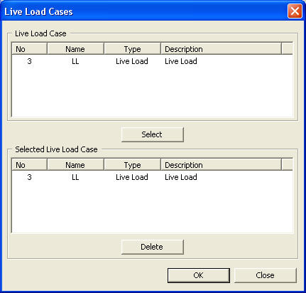
Live load case dialog box
Live Load Case
Display the live load cases entered during the generation of the analysis model.
![]()
![]()
Select the live load cases (including the roof live load) to be reduced from the Live Load Case field with the mouse and click ![]() to display the selected load cases in Selected Live Load Case.
to display the selected load cases in Selected Live Load Case.
 Selected Live Load Case
List the load cases for which the live load reduction factors are to be calculated.
![]() : Delete the load cases selected by the mouse from Selected Live Load Case.
: Delete the load cases selected by the mouse from Selected Live Load Case.
![]() : Enter the selected load cases and values and close the dialog box.
: Enter the selected load cases and values and close the dialog box.
![]() : Do not enter the selection and close the dialog box.
: Do not enter the selection and close the dialog box.