Define Pushover Hinge Properties
Define the plastic hinge data to be used in Pushover analysis.
Note
Hinge properties such as yield strength are calculated based on the specified design code in Design>Concrete/Steel Design Parameter>Design code.
From the Main Menu select Design > Pushover Analysis > Define Hinge Properties
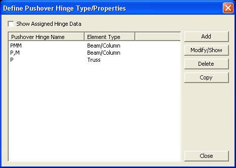
Define Pushover Hinge Data dialog box
Click the![]() button
to define plastic hinge information in the dialog box below. Click
the
button
to define plastic hinge information in the dialog box below. Click
the![]() button to confirm
or modify and the
button to confirm
or modify and the![]() button
to delete the data entry. Select the pushover hinge to be copied
in the dialog box and click
button
to delete the data entry. Select the pushover hinge to be copied
in the dialog box and click ![]() button.
button.
After defining the hinge type and
assigning it to the selected members, check on the Show Generated
Hinges in the Define Pushover Hinge Data dialog box to check the
automatically calculated hinge data by the section information.
Select the hinge data to be checked and click the![]() button to prompt the Add/Modify Hinge Data Type dialog box in
which the
button to prompt the Add/Modify Hinge Data Type dialog box in
which the![]() button is
clicked to check the hinge data. Corrections to the assigned hinge
data are not permitted here.
button is
clicked to check the hinge data. Corrections to the assigned hinge
data are not permitted here.
Note 1
When members are assigned hinge properties, inherent titles are assigned to the automatically generated hinge data. For example, "B1-PMM" represents:
B: Hinge assigned to a beam element
1: Sequential number assigned to by element types
Beam: Assigned hinge type (Beam, Column, PMM )
Note 2
Hinge
properties of each element are automatically generated according
to the sectional information. For reinforced concrete members,
reinforcing steel must be pre-determined through the design feature
in Gen. Reinforcing steel data for the relevant sections must
be provided in Modify Beam (Column, Brace & Wall) Section
Data of Concrete
Design Parameter. If the automatic
design feature for reinforced concrete members (Concrete
Code Design) is used, you are
required to enter the reinforcing data using the![]() button in the Design Result dialog box for each element.
button in the Design Result dialog box for each element.
Note 3
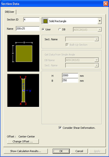
Strength calculation method for Value Type Steel Section
1. Sectional information such as Area, Asy, Asz, Cym, Cyp, Czm, Czp, Zyy, and Zzz cannot be 0 for auto-calculation
(Zyy, Zzz are new items added in Value Type and can be checked in Model > property > Section).
2. Hinge strength is calculated for P, My-Mz, Vy-Vz, and PMM.
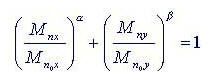
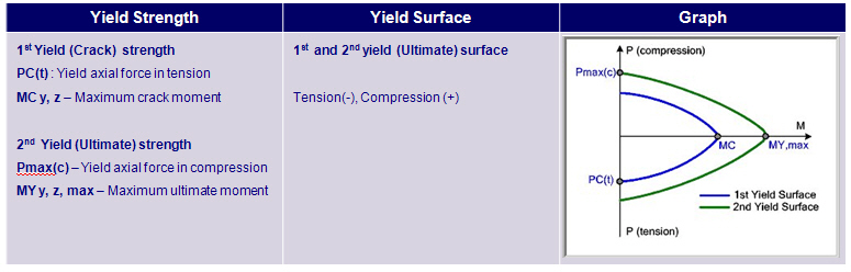
3. For Yielding, the PM-Curve is generated on the basis of Pc (compressive strength), Pt (tensile strength), and M0 (flexural
strength at P=0, or Fy×yy, Fy×zz).
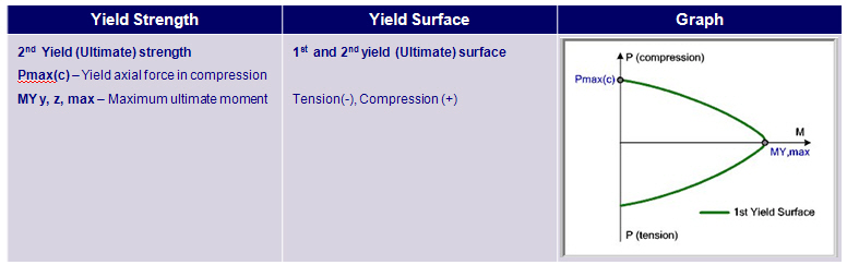
4. For Ultimate, the PM-Curve is generated on the basis of Pc (compressive strength), Pt (tensile strength), and M0 (flexural
strength at P=0, or Fy×Zyy, Fy×zz).
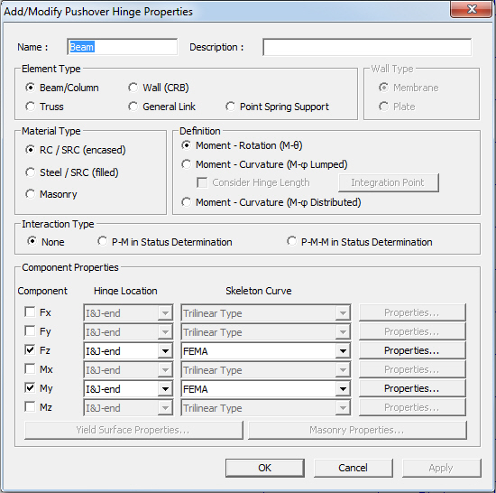
Add/Modify Hinge Data Type dialog box
 Hinge Properties Type
Name
Hinge Properties Type
Name
Define names of plastic hinge properties.
Description
State a brief description related to the pushover hinge properties.
![]() Element Type
Element Type
Specify the type of element.
Beam/Column : Beam or Column element
Wall : Wall element
Truss : Truss element
General Link : Spring which can be defined at Model>Boundaries>Define General Link Properties
Point Spring Support : Point Spring Support
![]() Wall Type
Wall Type
Specify the type of wall element.
Membrane : Only in-plane plasticity is considered
Plate : Both in-plane and out-of-plane plasticity are considered
![]() Material Type
Material Type
Specify the type of material used to the corresponding element.
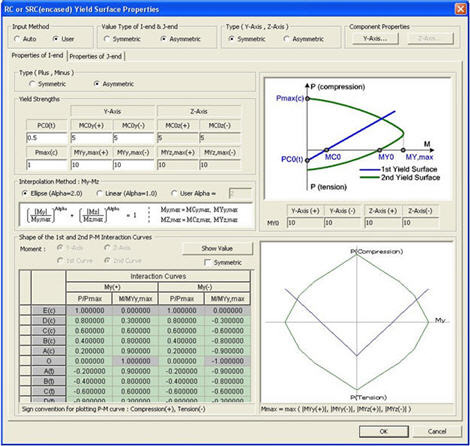
RC / SRC (encased) : RC or SRC (Steel-encased concrete type)
Steel / SRC (filled) : Steel or SRC (Concrete-filled steel tube type)
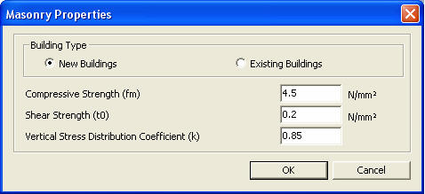
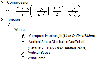
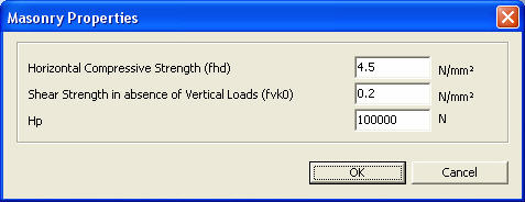
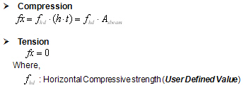
Masonry : Masonry type
![]() Definition
Definition
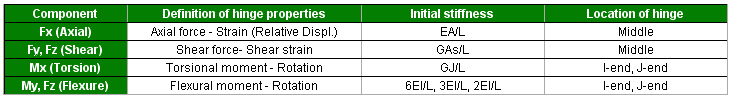
Specify the load-deformation relationship of the flexural member.
Moment-Rotation (M-θ)
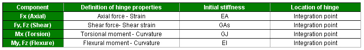
Moment-Curvature (M-φ Lumped)
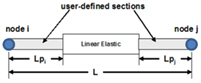
Consider Hinge Length : Check on to assign pushover hinge to the specified hinge length.
Integration Point : Select the integration point location to End or Center of the hinge length.
<When Integration Point is “End”>
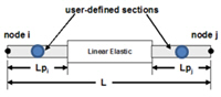
<When Integration Point is “Center”>
Moment-Curvature (M-φ Distributed)
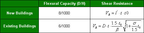
Pier Type : For vertical members in the masonry material type. Hinge properties are defined in terms of moment-rotation
relationship for a members section.
Spandrel Type : For horizontal members in the masonry material type. Hinge properties are defined in terms of moment-
rotation relationship for a members section.
![]() Interaction Type
Interaction Type
None : Axial force and biaxial moments are uncoupled from each other.
P-M in Status Determination : Coupled axial force-uniaxial moment behavior is reflected by calculating the flexural yield strength of a hinge considering the effect of axial force.
P-M-M in Status Determination : Coupled axial force-biaxial moment behavior is reflected by calculating the flexural yield strength of a hinge considering the effect of axial force.
Component Properties
Fx, Fy, Fz, Mx, My, Mz : Check on the degree of freedom to be assigned to the plastic hinge type.
Hinge Location : Specify the hinge location within the corresponding element.
Number of Section : Specify the number of integration points when Definition is selected as 'Moment-Curvature (M-φ Distributed)'.
Skeleton Curve : Specify the skeleton curve.
Note 1
The skeleton curves available are as follows:
1. Bilinear Type (or Slip Bilinear Type)
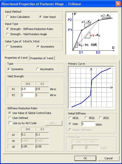
2. Trilinear Type (or Slip Trilinear Type).
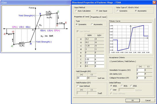
3. FEMA Type
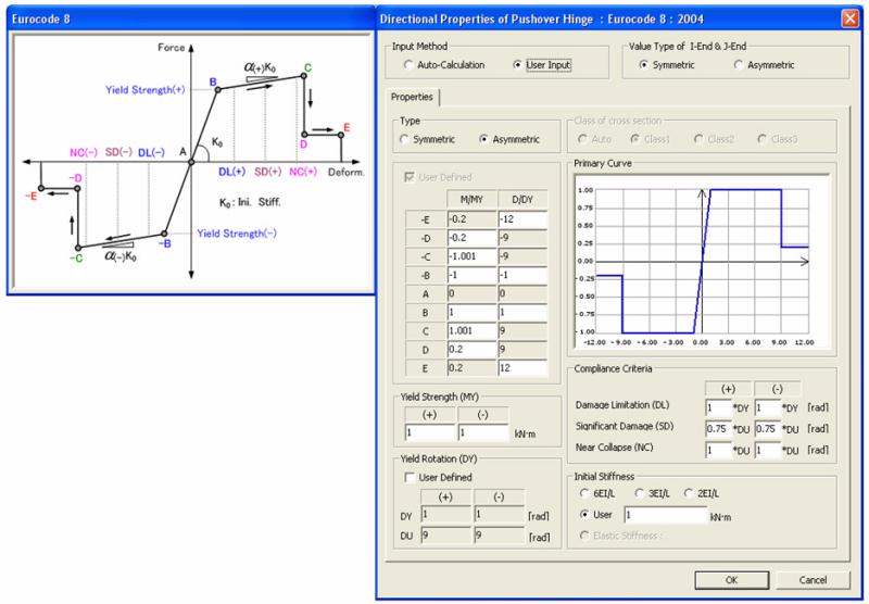
4. Eurocode8:2004
Slip Bilinear Type or Slip Trilinear Type is activated when the Element Type is defined as 'Truss' or 'General Link'.
Note 2
The Multi-Linear Type is applicable for both the load control and the displacement control methods and both FEMA and Eurocode 8 type is applicable only for the displacement control method.
![]()
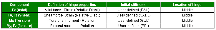
Enter the relevant hinge properties in the following dialog box:
Note Hinge properties by Element Types and Definitions
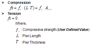
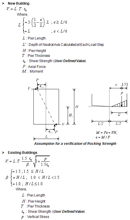
Masonry Properties
In the structural model, masonry spandrels may be taken into account as coupling beams between two wall elements. This assumption implies that they should regularly bonded to the adjoining walls and connected both to the floor tie beam and to the lintel below. If the structural model takes into account the coupling beams, a frame analysis may be used for the determination of the action effects on the vertical and horizontal structural elements.