Plate Forces/Moments
Check the distribution of member forces per unit length in plate elements in Contours or Vectors.
From the Main Menu select Results > Forces > Plate Forces/Moments.
Select Results > Forces > Plate Forces/Moments in the Menu tab of the Tree Menu.
Click ![]() Plate Forces/Moments in
the Icon
Menu.
Plate Forces/Moments in
the Icon
Menu.
|
Select a desired load case, load combination or envelope case.
Click
Step
Note 1
Note 2 When pushover analysis is performed for a structure containing Plate, Plane Stress or Solid elements, the pushover analysis results for Plate, Plane Stress or Solid elements can be produced by 'Steps'.
Local: Produce the contour representing member forces per unit width in the plate element local coordinate system.
UCS: Produce the contour representing member forces per unit width in the User-defined Coordinate System for the plate elements placed parallel to the x-y plane in UCS. If UCS has not been defined GCS is applied.
Element: Display the contour using the internal forces calculated at each node of an element.
Avg. Nodal: Display the contour using the average internal nodal forces of the contiguous elements sharing the common nodes.
Note Avg.Nodal does not consider the simultaneity for the load case in which maximum member forces are displayed about all elements such as Moving Load Case, Settlement Load Case and Time History Load Case.
Avg. Nodal Active Only: Execute Avg. Nodal for only currently active elements. |
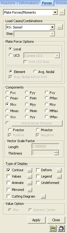
 Components
Select the desired internal force component among the following:
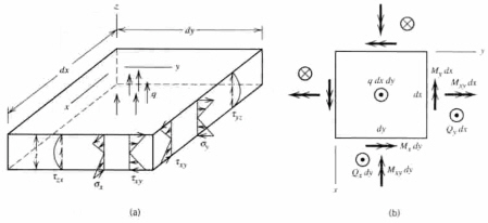
(a) Forces per unit length due to in-plane actions at the output locations
(b) Moments per unit length due to out-of-plane bending actions at the output locations
Output of plate elements forces per unit length
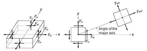
Fxx: Axial force per unit width in the element's local or UCS x-direction (Perpendicular to local y-z plane)
Fyy: Axial force per unit width in the element's local or UCS y-direction (Perpendicular to local x-z plane)
Fxy: Shear force per unit width in the element's local or UCS x-y direction (In-plane shear)
Fmax: Maximum Principal Axial Force per unit width
Fmin: Minimum Principal Axial Force per unit width
FMax: Maximum absolute Principal Axial Force per unit width
Mxx: Bending moment per unit width in the direction of the element's local or UCS x-axis (Out-of-plane moment about local y-
axis)
Myy: Bending moment per unit width in the direction of the element's local or UCS y-axis (Out-of-plane moment about local x-
axis)
Mxy: Torsional moment per unit width about the element's local or UCS x-y plane
Mmax: Maximum principal bending moment per unit width
Mmin: Minimum principal bending moment per unit width
MMax: Maximum absolute Principal Moment per unit width (Larger magnitude of Mmax and Mmin)
Vxx: Shear force per unit width in the thickness direction along the element's local or UCS y-z plane
Vyy: Shear force per unit width in the thickness direction along the element's local or UCS x-z plane
VMax: Maximum absolute shear force per unit width (Larger magnitude of Vxx and Vyy)
![]() : Display the combination of bending
moment (Mxx or Myy) and torsional moment (Mxy).
: Display the combination of bending
moment (Mxx or Myy) and torsional moment (Mxy).
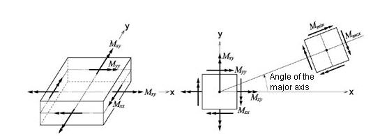
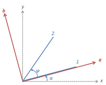
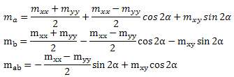
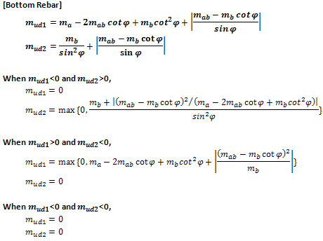
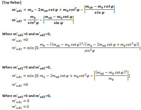
Note. Wood-Armer
formula for skew reinforcement
Fvector: Representation of maximum and minimum principal force directions and the larger absolute magnitude at the centers of plate elements
Mvector : Representation of maximum and minimum principal moment directions and larger absolute magnitude at the centers of plate elements
Vector Scale Factor: Drawing scale for the vector diagram
(a) Force per unit length due to in-plane behavior
(b) Moment per unit length due to out-of-plane behavior
Type of Display
Define the type of display as follows :
Value Option
Select an option to produce the absolute maximum value or the force at the center.
Max: Display the absolute maximum value among the forces of a plate element.
Element Center: Display the force at the center of a plate element.
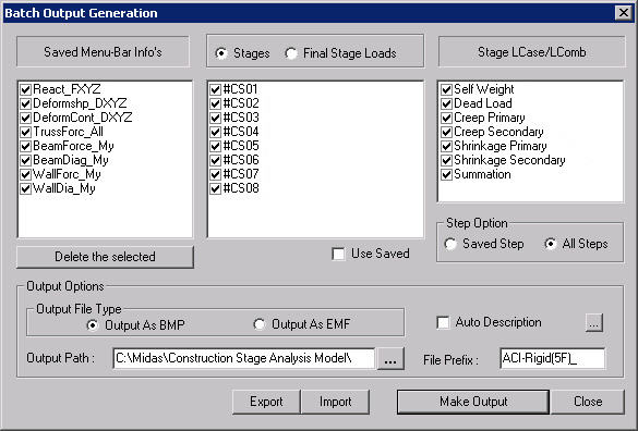
Batch Output Generation
(  ,
,  )
)
Given the types of analysis results for Graphic outputs, generate consecutively graphic outputs for selected load cases and combinations. A total number of files equal to the products of the numbers of checked items in the three columns of the dialog box below are created. (Details...)
![]() Revision
of Gen 2014 (v1.1)
Revision
of Gen 2014 (v1.1)
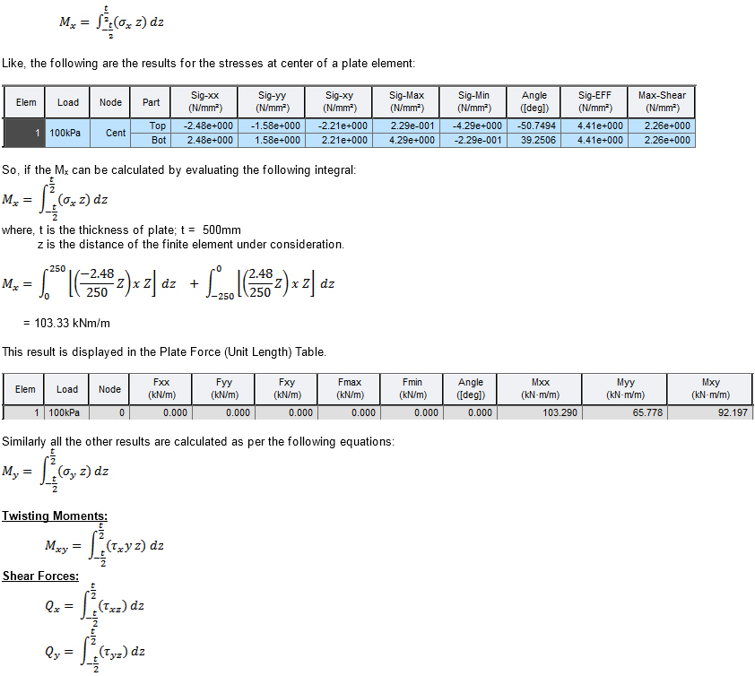
Q1. How can I obtain the results for Plate Force (Unit Length)?